 | Coloring a point cloud using 3DF Zephyr
Welcome to the 3DF Zephyr tutorial series. In the following tutorial you will learn how to: import a point cloud collected by using laser scanner equipment align that with the point cloud you generate with 3DF Zephyr color the laser scanner cloud; This is an old tutorial for Zephyr 2.x |
This feature is available in 3DF Zephyr Pro and 3DF Zephyr Aerial only. Click here to view this tutorial for older 3DF Zephyr versions.

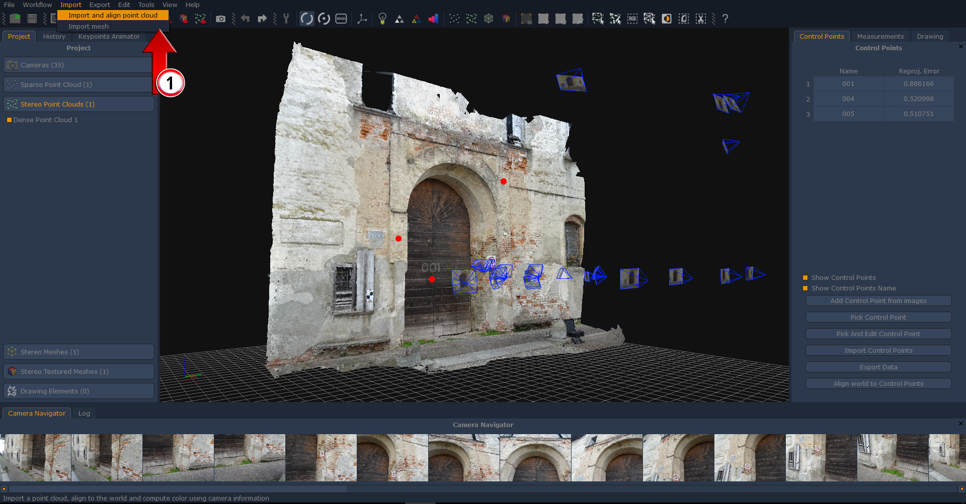
You are supposed to generate your dense point cloud first – picture 1 – as there is the need to get a 3D entity before importing anything else and to placing at least three control points so as to achieve the alignment.
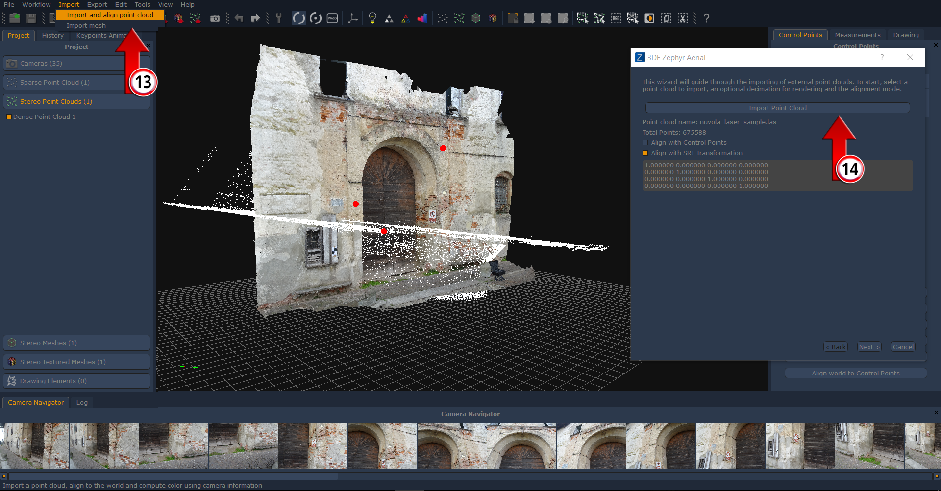
Once the dense point cloud is done just click on “Import” in the menu bar and select then the “Import and align point cloud” (1) option.
Within the new dialog you can choose among two different alignment methods, either through control points or through SRT (scale-rotate-traslate) transformation.
Make sure to follow only one of the proposed methods.
CONTROL POINTS ALIGNMENT
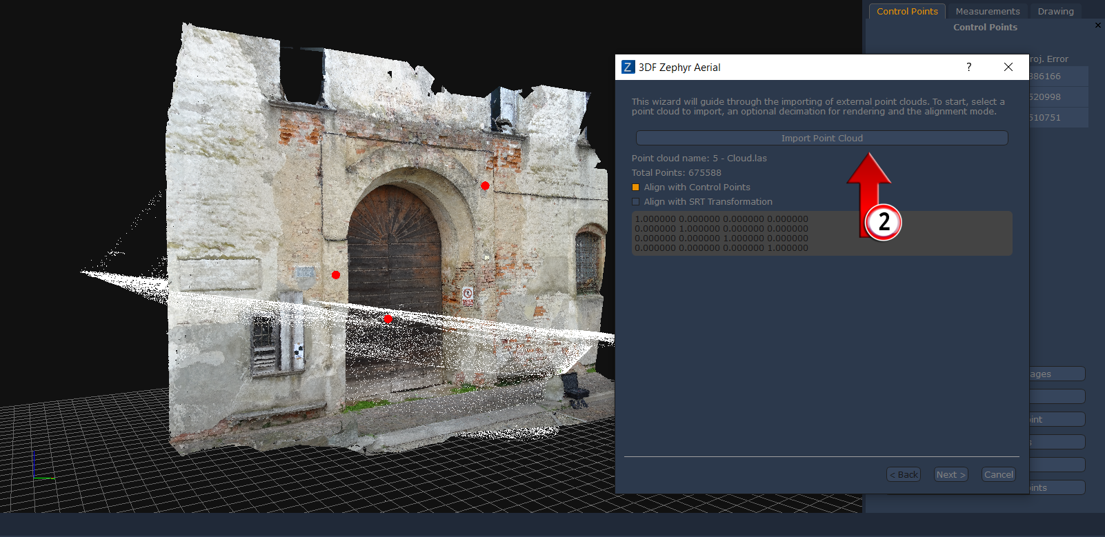
After clicking on “Import point cloud button” (2) and picking your data (six file formats available) you can select the control points alignment procedure – picture 2 – and click on “Next” button.
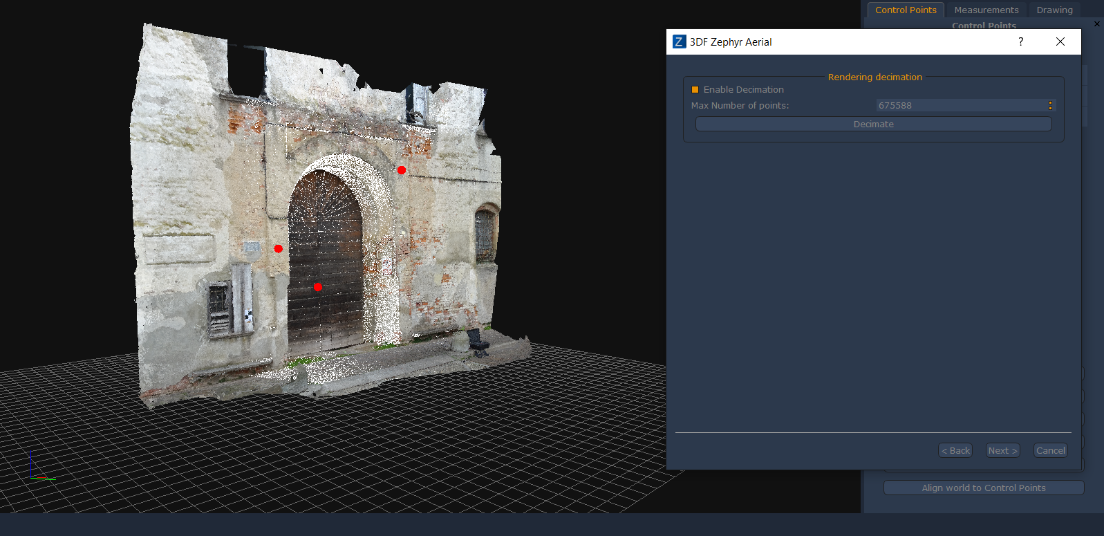
You will notice that the cloud you chose will come up inside 3DF Zephyr as a white element at this stage.
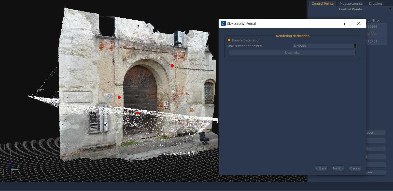
In the next window – picture 3 – you are allowed to enable the decimation tool if the imported point cloud is a huge one (several million points). That option is deactivated by default.
Click on “Next” button to move forward.
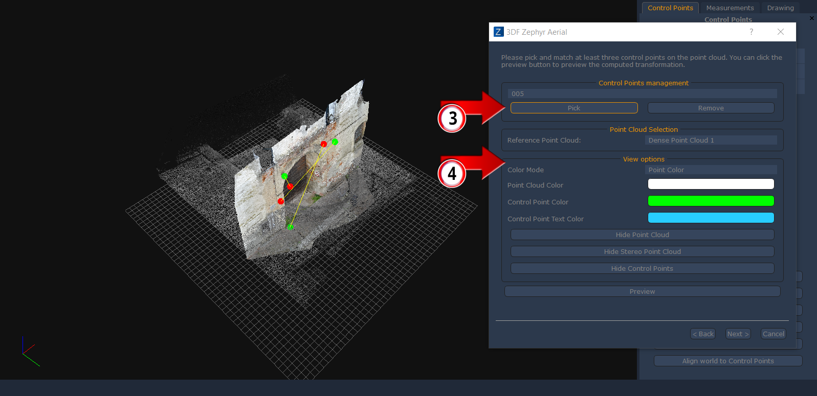
Let’s take a look at the following dialog – picture 4 – that is arranged in three sections:
– the “control points management” section (3) allows you to place the corresponding control points on the laser scanner point cloud one by one and to link them to the points you located before on the Zephyr dense cloud.
– the “view options” (4) section let you select how you want to see the imported cloud (color or reflectivity info). Buttons below allow to hide or show up the point clouds.
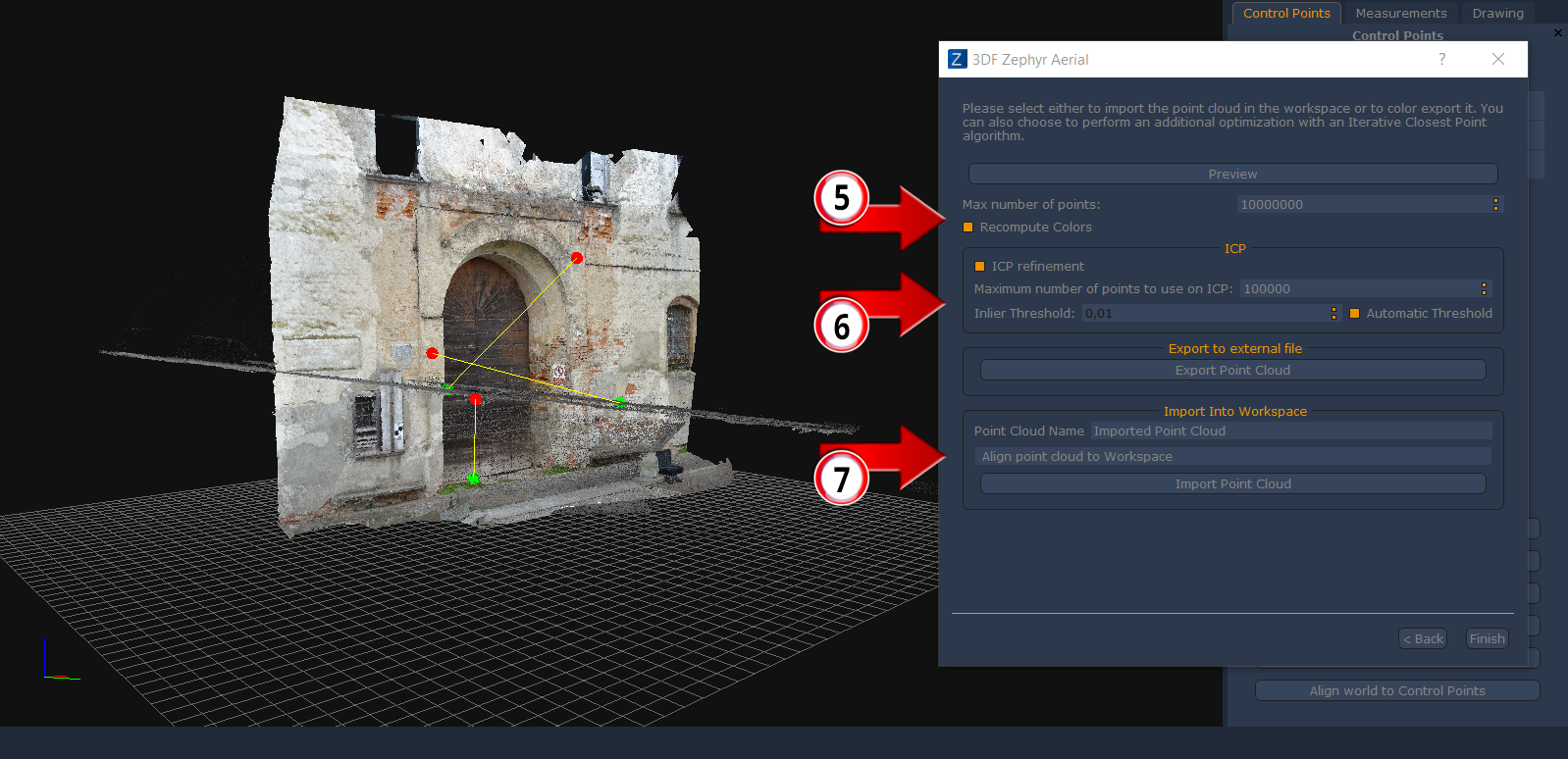
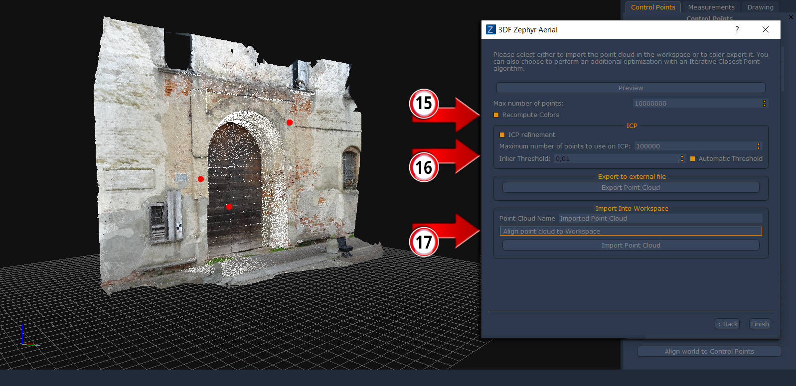
When control points matching is done click on “Next” button to deal with the last tool window – picture 5 – The “recompute colors” (5) option is activated by default: it’s able to add color information to the laser scanner point cloud.
ICP algorithm – Iterative Closest Point – (6) allows to improve the alignment precision but you should not exploit it when you are tinkering with planar surfaces only.
Inside the Import section (7) you can choose which point cloud will be the reference and wich cloud will be moved so as to be aligned.
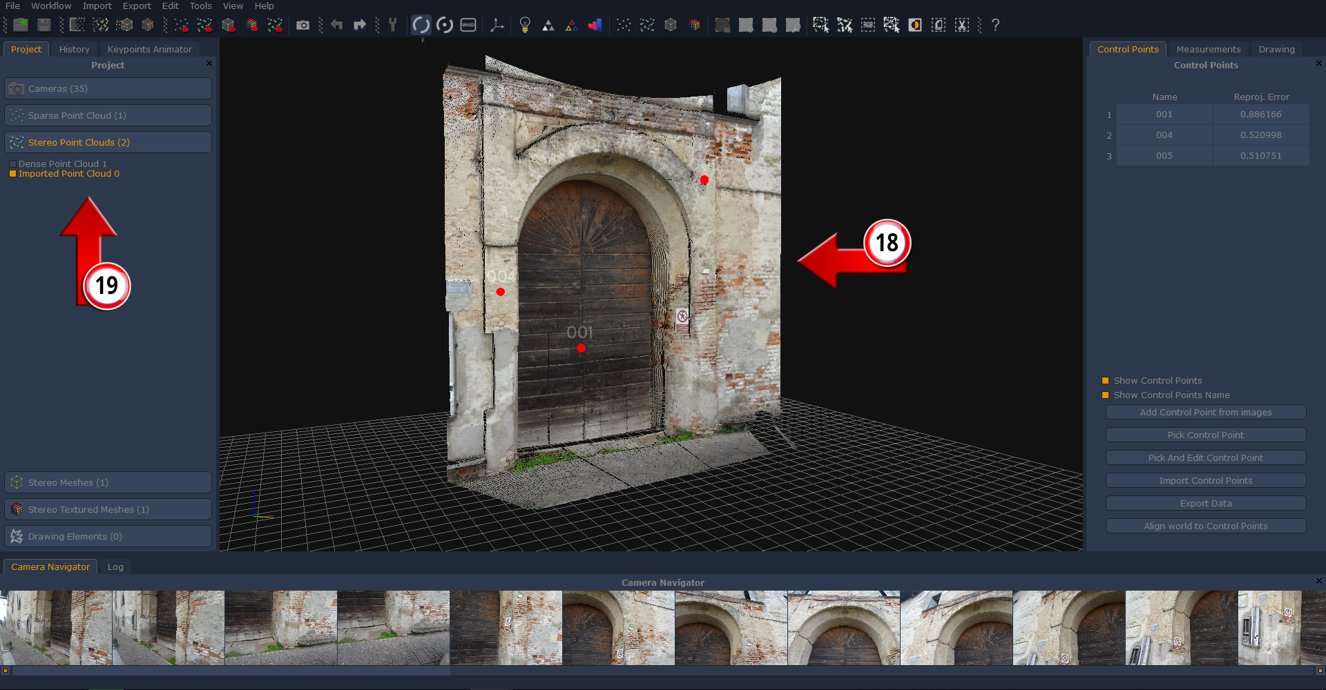
Finally you can click on “import point cloud” to complete the procedure and you’ll notice that the laser scanner cloud will be listed into the project window on the left side of Zephyr interface.
Clearly it is possible to merge both the point clouds and running then the mesh generation step.
SRT TRANSFORMATION ALIGNMENT
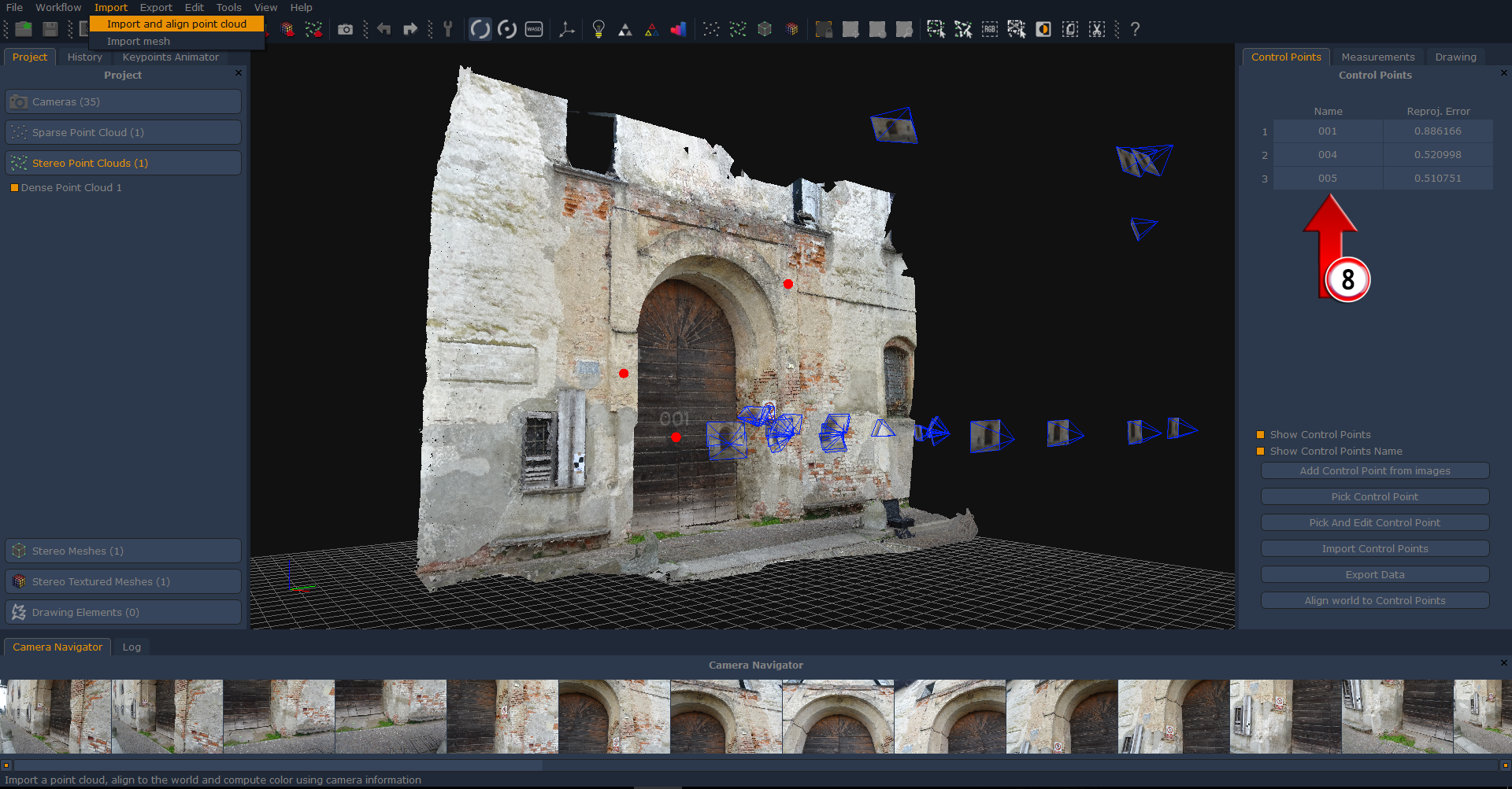
You are supposed to generate your dense point cloud first – picture 6 – as there is the need to get a 3D entity before importing anything else and to placing at least three control points (8) so as to achieve the alignment.
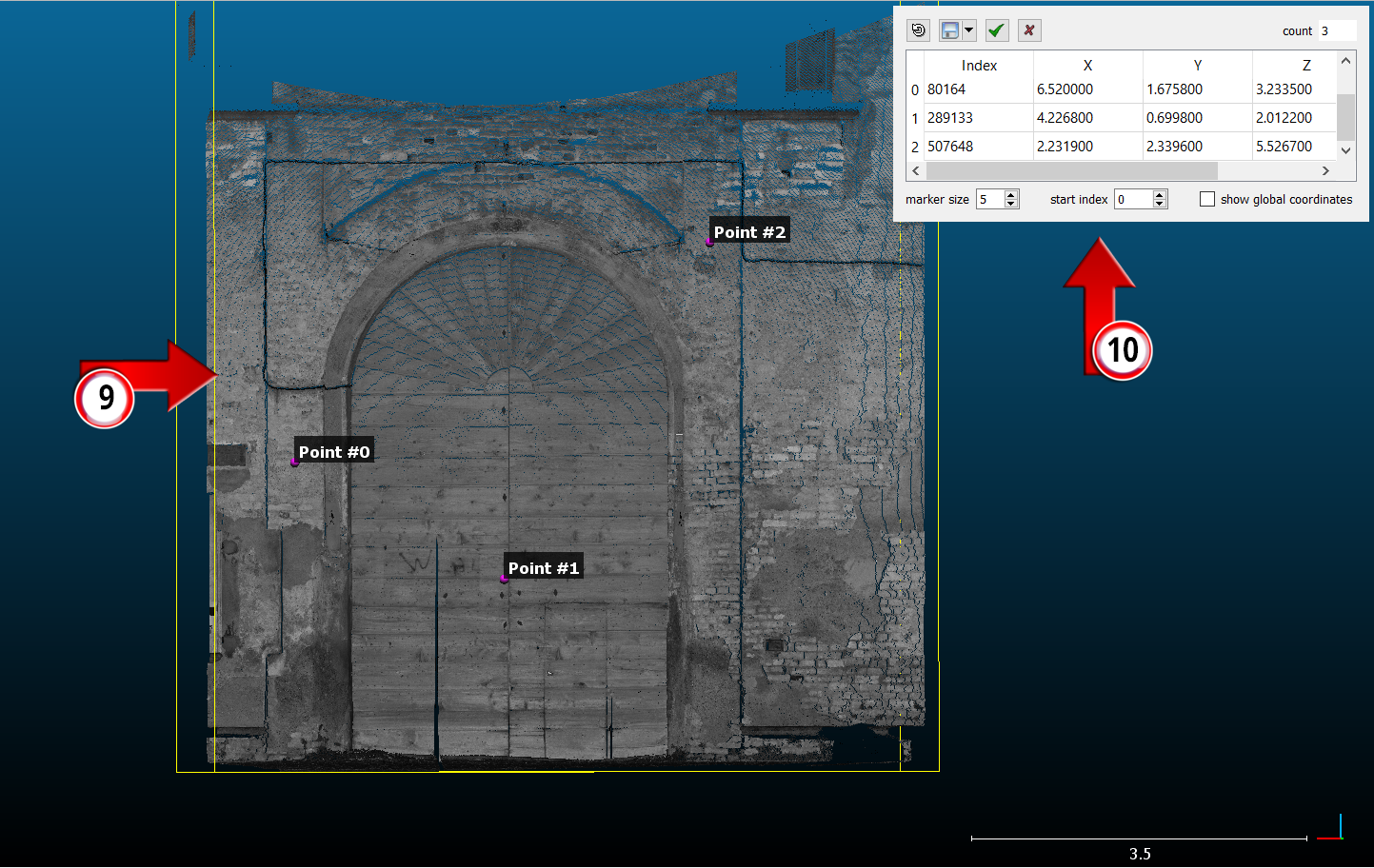
In this alignment procedure we are going to use CloudCompare – picture 7 – to perform the following step.
Import your laser scanner cloud in Cloud Compare and find then as many control points as you placed on the dense cloud in Zephyr. Each point must have the same position and name (9) of the previous identified. Once the individuation is done you can save the point list (10) as a .txt file.
In this case point #0, point #1 and point #2 must be renamed as 001, 004 and 005 inside the .txt file.
Now let’s go back to Zephyr!
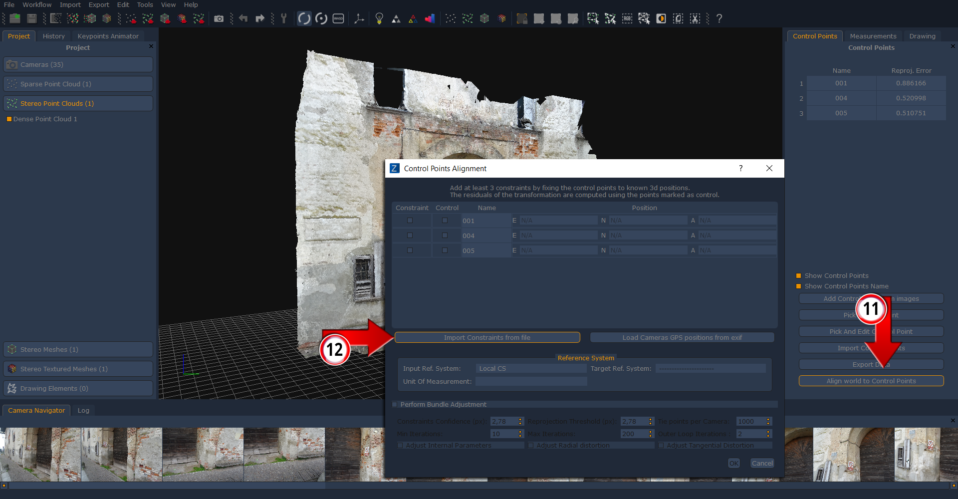
Simply click on the “align world to Control points” (11) button in order to open the window where it is possibile to import the .txt file we have previuosly generated in CloudCompare by clicking on the “import constraints from file” (12) button.
The aim of this step is giving Zephyr point cloud the same reference system (and dimensions too) of the laser scanner cloud.
Click on “Import point cloud” button (13) and pick your laser scanner cloud (six file formats available) and select the SRT transformation alignment procedure (14) and then move forward with the “Next” button.
You will notice that the cloud you have chosen will come up inside 3DF Zephyr as a white element at this stage – picture 9 –
In the next window- picture 10 – you are allowed to enable the decimation tool if the imported point cloud is a huge one (several million points). That option is deactivated by default.
You will notice that the imported cloud will be already aligned to the Zephyr cloud.
Click then on “Next” button to move forward.
In this last window the “recompute colors” (15) option is activated by default: it’s able to add color information to the laser scanner point cloud if that misses at the beginning.
ICP algorithm – Iterative Closest Point – (16) allows to improve the alignment precision but you should not exploit it when you are tinkering with planar surfaces only.
Inside the Import section (17) you can choose which point cloud will be the reference and wich cloud will be moved so as to be aligned.
Now you can click on “import point cloud” button and the result will be featured into the rendering area (18) of Zephyr – picture 12 – while the laser cloud will be listed below the dense point cloud entry in the Project tab (19) on the left side of Zephyr main interface.
Clearly it is possible to merge both the point clouds and running then the mesh generation step.
The next tutorial will show how generate contour lines and sections. Proceed to the next tutorial.