Elements of Computer Vision: Multiple View Geometry.

§ 3. Pin-hole Camera Geometry

The pin-hole camera is described by its optical centre C (also known as camera projection centre) and the image plane. The distance of the image plane from C is the focal length f. The line from the camera centre perpendicular to the image plane is called the principal axis or optical axis of the camera. The plane parallel to the image plane containing the optical centre is called the principal plane or focal plane of the camera. The relationship between the 3-D coordinates of a scene point and the coordinates of its projection onto the image plane is described by the central or perspective projection.

Figure 2. Pin-hole camera geometry. The left figure illustrates the projection of the point M on the image plane by drawing the line through the camera centre C and the point to be projected. The right figure illustrates the same situation in the XZ plane, showing the similar triangles used to compute the position of the projected point m in the image plane.

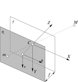
A 3-D point is projected onto the image plane with the line containing the point and the optical centre (see Figure 2).

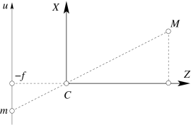
Let the centre of projection be the origin of a Cartesian coordinate system wherein the z-axis is the principal axis.

By similar triangles it is readily seen that the 3-D point x,y,zT is mapped to the point fx/z,fy/zT on the image plane.

§ 3.1. The camera projection matrix

If the world and image points are represented by homogeneous vectors, then perspective projection can be expressed in terms of matrix multiplication as

fxfyz=f0000f000010xyz1 (3)

The matrix describing the mapping is called the camera projection matrix P.

Equation (3) can be written simply as:

zm=PM (4)

where M=x,y,z,1T are the homogeneous coordinates of the 3-D point and m=fx/z,fy/z,1T are the homogeneous coordinates of the image point.

The projection matrix P in Eq. (3) represents the simplest possible case, as it only contains information about the focal distance f.

§ 3.1.1. General camera: bottom up approach

The above formulation assumes a special choice of world coordinate system and image coordinate system. It can be generalized by introducing suitable changes of the coordinates systems.

Changing coordinates in space is equivalent to multiplying the matrix P to the right by a 4×4 matrix:

G=Rt01 (5)

G is composed by a rotation matrix R and a translation vector t. It describes the position and orientation of the camera with respect to an external (world) coordinate system. It depends on six parameters, called extrinsic parameters.

The rows of R are unit vectors that, together with the optical centre, define the camera reference frame, expressed in world coordinates.

Changing coordinates in the image plane is equivalent to multiplying the matrix P to the left by a 3×3 matrix:

K=f/sxf/sxcotθox0f/syoy001 (6)

K is the camera calibration matrix; it encodes the ransformation in the image plane from the so-called normalized camera coordinates to pixel coordinates.

It depends on the so-called intrinsic parameters:

  • focal distance f (in mm),

  • principal point (or image centre) coordinates ox,oy (in pixel),

  • width (sx) and height (sy) of the pixel footprint on the camera photosensor (in mm),

  • angle θ between the axes (usually π/2).

The ratio sy/sx is the aspect ratio (usually close to 1).

Thus the camera matrix, in general, is the product of three matrices:

P=K[I|0]G=K[R|t] (7)

In general, the projection equation writes:

ζm=PM (8)

where ζ is the distance of M from the focal plane of the camera (this will be shown after), and m=u,v,1T.

Note that, except for a very special choice of the world reference frame, this “depth” does not coincide with the third coordinate of M.

§ 3.1.2. General camera: top down approach

If P describes a camera, also λP for any 0λR describes the same camera, since these give the same image point for each scene point.

In this case we can also write:

mPM (9)

where means “equal up to a scale factor.”

In general, the camera projection matrix is a 3×4 full-rank matrix and, being homogeneous, it has 11 degrees of freedom.

Using QR factorization, it can be shown that any 3×4 full rank matrix P can be factorised as:

P=λK[R|t], (10)

(λ is recovered from K3,3=1).

§ 3.2. Camera anatomy

§ 3.2.1. Projection centre

The camera projection centre C is the only point for which the projection is not defined, i.e.:

PC=PC~1=0 (11)

where C~ is a 3-D vector containing the Cartesian (non-homogeneous) coordinates of the optical centre.

After solving for C~ we obtain:

C~=-P1:3-1P4 (12)

where the matrix P is represented by the block form: P=[P1:3|P4] (the subscript denotes a range of columns).

§ 3.2.2. Depth of a point

We observe that:

ζm=PM=PM-PC=PM-C=P1:3M~-C~. (13)

In particular, plugging Eq. (10), the third component of this equation is

ζ=λr3TM~-C~

where r3T is the third row of the rotation matrix R, which correspond to the versor of the principal axis.

If λ=1, ζ is the projection of the vector M~-C~ onto the principal axis, i.e., the depth of M.

§ 3.2.3. Optical ray

The projection can be geometrically modelled by a ray through the optical centre and the point in space that is being projected onto the image plane (see Fig. 2).

The optical ray of an image point m is the locus of points in space that projects onto m.

It can be described as a parametric line passing through the camera projection centre C and a special point (at infinity) that projects onto m:

M=-P1:3-1P41+ζP1:3-1m0,ζR. (14)

If λ=1 the parameter ζ in Eq. (14) represent the the depth of the point M.

Knowing the intrinsic parameters is equivalent to being able to trace the optical ray of any image point (with P=[K|0]).

§ 3.2.4. Image of the absolute conic

We will prove now that the image of the absolute conic depends on the intrinsic parameters only (it is unaffected by camera position and orientation).

The points in the plane at infinity have the form M=M~T,0T, hence

mK[R|t](M~T,0)T=KRM~. (15)

The image of points on the plane at infinity does not depend on camera position (it is unaffected by camera translation). The absolute conic (which is in the plane at infinity) has equation M~TM~=0, therefore its projection has equation:

mTK-TK-1m=0. (16)

The conic ω=KKT-1 is the image of the absolute conic.

Its knowledge allows one to measure metrical properties, such as the the angle between two rays.

Figure 3. Angle θ between two rays.

Indeed, let us consider a camera P=[K|0]. Then the angle θ between the rays trough M1 and M1 is:

cosθ=M~1TM~2M~1M~2=m1Tωm2m1Tωm1m2Tωm2 (17)

(it follows easiyl from m=1zKM~.)

§ 3.3. Camera calibration (or resection)

A number of point correspondences miMi is given, and we are required to find a camera matrix P such that

miPMifor all i. (18)

The equation can be rewritten in terms of the cross product as

miPMi=0. (19)

This form will enable a simple a simple linear solution for P to be derived. Using the properties of the Kronecker product () and the vec operator (Magnus and Neudecker,1999), we derive:

mi×PMi=0[mi]×PMi=0vec([mi]×PMi)=0(MiT[mi]×)vecP=0

These are three equations in the 12 unknown of vecP. However, only two of them are linearly independent: Indeed, the rank of MiTmi× is two because it is the Kronecker product of a rank-1 matrix by a a rank-2 matrix. Therfore, from a set of n point correspondences one obtains a 2×n×12 coefficient matrix A by stacking up two equations for each correspondence. In general A will have rank 11 (provided that the points are not all coplanar) and the solution is the 1-dimensional right null-space of A. The projection matrix P is computed by solving the resulting linear system of equations, for n6.

If the data are not exact (noise is usually present) the rank of A will be 12 and a least-squares solution for vecP is conputed as the singular vector corresponding to the smallest singular value of A. This is called the Direct Linear Transform (DLT) algorithm in (Hartley and Zisserman,2003).