DEM viewer and elevation profile
These functions are not available in 3DF Zephyr Lite and 3DF Zephyr Free.
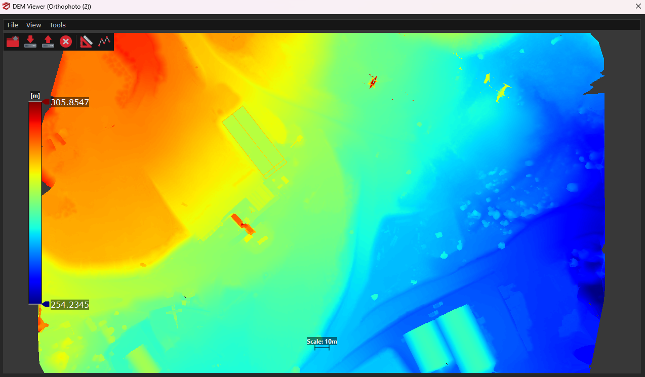
The DEM viewer utility allows viewing DSM and DTM files directly from the Zephyr UI.
Please note that you are supposed to generate an orthophoto before running DEM generation. To do so, simply click on Workflow > Generate True Orthophoto from Mesh and follow the wizard for the orthophoto generation.
The DEM viewer utility can be used to:
- load DSM / DTM and multi-tiled DSM/DTM files (even those not related to the project you are working on) by clicking on File > Open from file or Open from workspace;
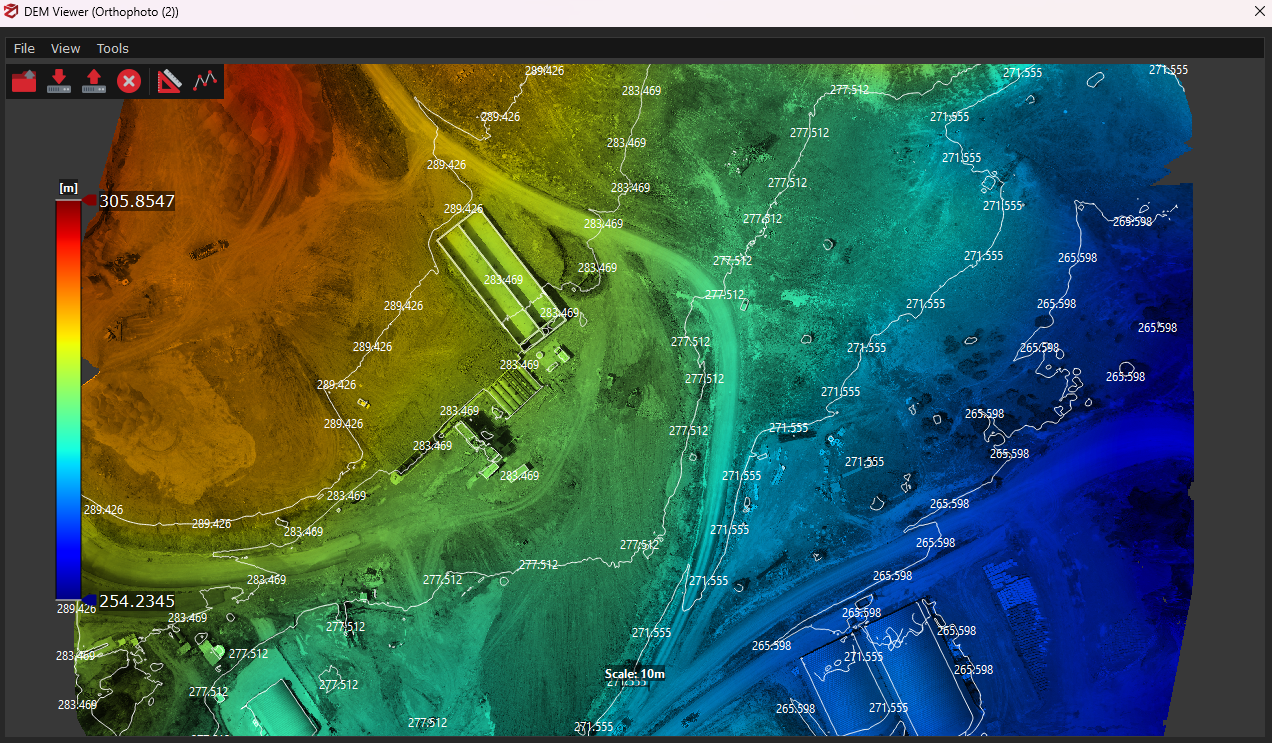
- load contour lines on DSM / DTM if they have been previously generated in 3DF Zephyr, by clicking on View > Show polylines;
- export DSM /DTM as an image (available formats: .png, .jpg, .bmp) by clicking on File > Export color image;
- generate elevation profiles;
DSM/DTM files and orthophotos are loaded together automatically, provided they are located in the same directory. Here is an example of contour lines, DEM and orthophoto mixed together inside DEM viewer:
Elevation profile generation
You can generate elevation profiles in the DEM Viewer utility provided that you have already created an orthophoto/DSM/DTM (not necessarily related to the project you are working on).
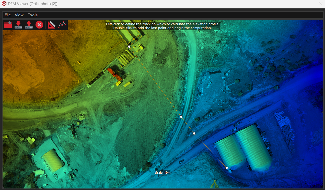
Simply click on the Elevation Profile icon and pick at least two points on the DSM/DTM. Double-click to add the last point and open the setup page. You will notice both the quota and progressive entries are already listed into the chart.
In the setup page you can:
- define the step size and number (distance between each quota/progressive value) in meters;
- add/delete/edit/move up/move down your quota, progressive, latitude or longitude entries clicking the related button;
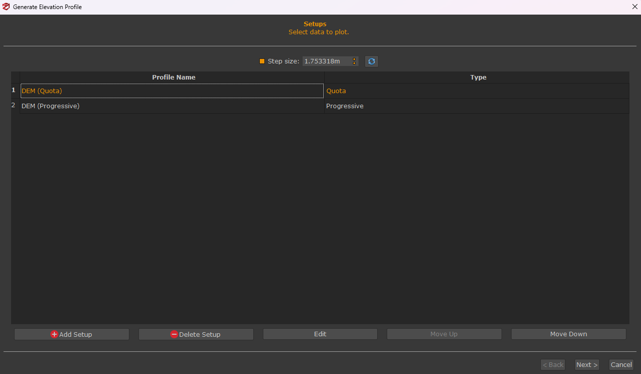
Click Next to select the profile you want to generate from the drop-down menu on the preview page, and the elevation profile will be automatically created.
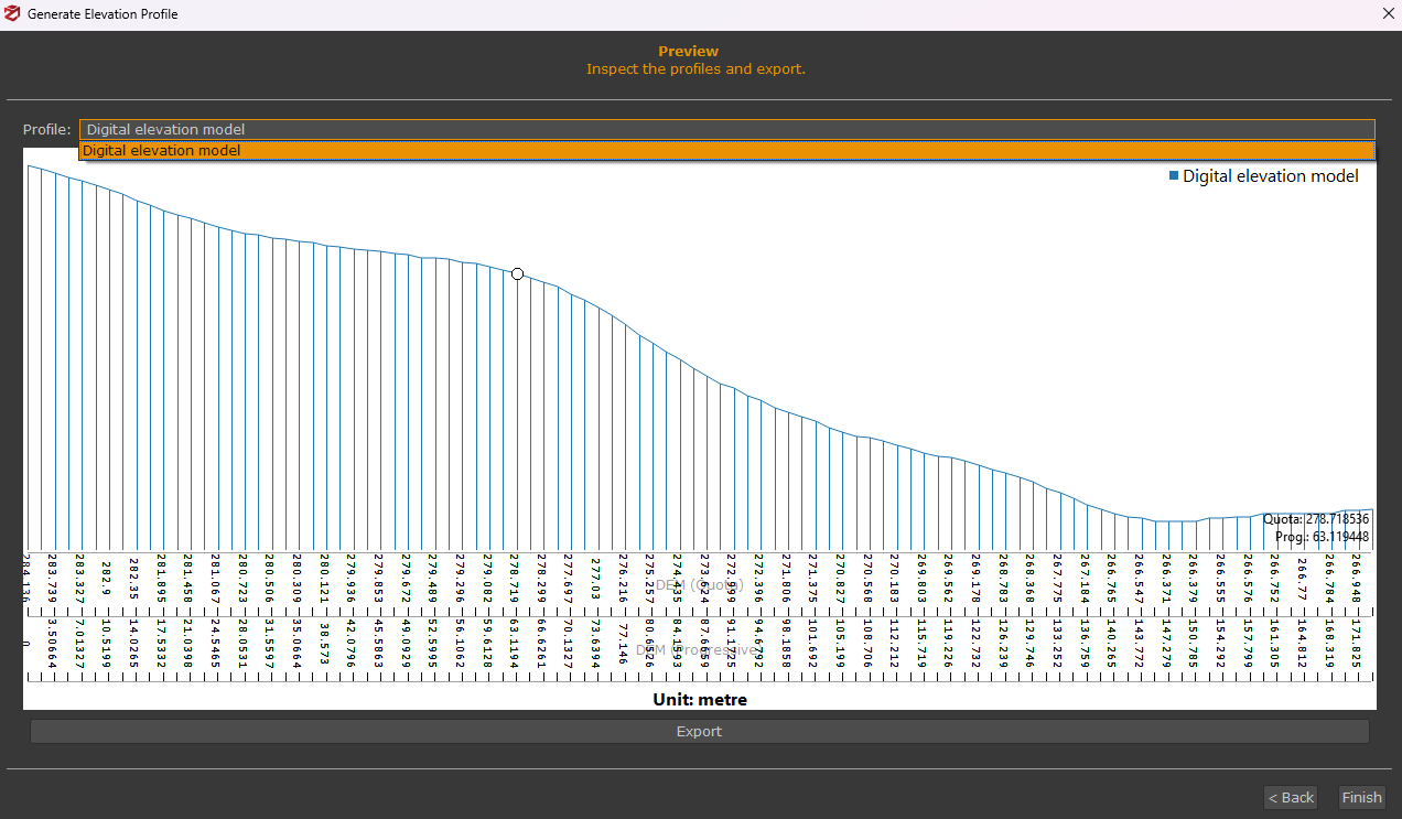
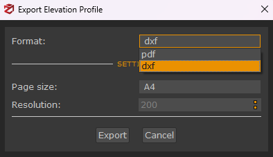
You can click the Export button to select the desired format (.pdf, .dxf) as well as the page size and resolution of the .pdf layout.
*TIPS*
- you can generate an elevation profile from a polyline you have already drawn by clicking Tools > Sections and Contour lines > Elevation profile from drawing elements and selecting the desired drawing element using the Add button in the Setup page.
- you can generate an elevation profile from a group of control points you have previously placed on the 3D model by clicking Tools > Lines extraction > make polyline from control points and continuing the above workflow to generate an elevation profile from a polyline.
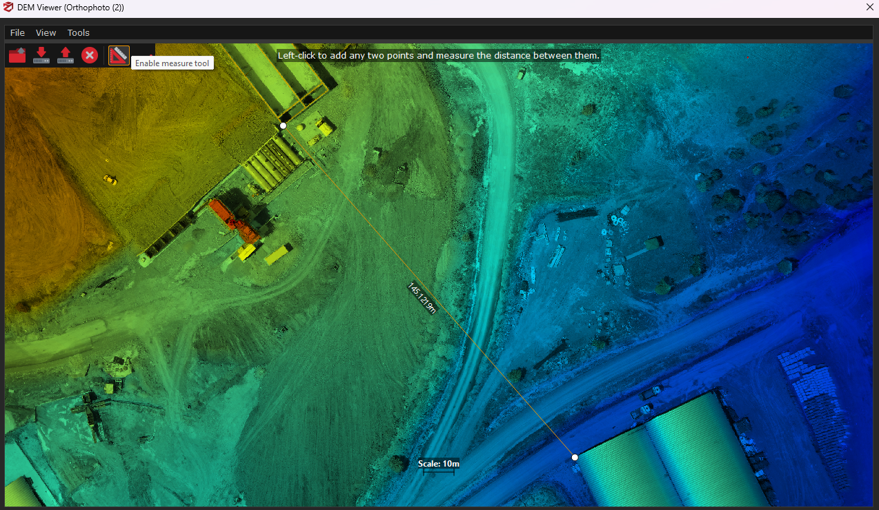
You can also calculate distances on the DSM/DTM by clicking on the Enable measure tool icon and picking two points on it.
The corresponding distance (meters) will be displayed next to the drawn polyline (see the image below).