Tools - Workspace
The Workspace menu allows for running tools dedicated to 3D objects management and pictures used in the 3D reconstruction:
- Scale/Rotate/Translate Objects: this tool opens a window that allows the user to scale/rotate/translate the 3D models (clouds and meshes) either by inserting your desired values or by using the 3D gizmo performing a manual transformation.
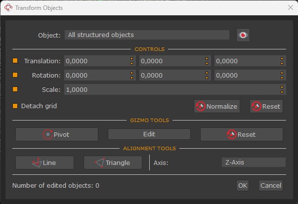
Besides, from this window, you can also edit the pivot of your gizmo, and find other alignment tools such as:
- Define the up axis by drawing a line: allows drawing of a single segment directly on the 3D model to be aligned with the desired axis (the drawing must be done on an element of the 3D model that is actually on the up vector in the real world, such as a wall in a building).
- Define the up axis by drawing a triangle base: allows drawing of a triangle (a plane) from which the Z axis will be computed (the plane must be done on an element of the 3D model that is actually on the horizontal axis in the real world, such as the ground). After picking the second point in the plane, two arrows will be rendered on the screen, one that will show the selected axis (blue arrow) and the normal direction of the plane (light blue arrow). In order to correctly align the axis, the two arrows must match.
Please note: the Reset tool in the "Controls" section allows for resetting the gizmo to the initial state, whereas the Reset tool in the "Gizmo tools" section resets the gizmo independently from the 3D object.
- Transform Rendering Reference System: allows to scale/translate the 3D viewport.
- Define the up vector with control points: this tool opens a windows that allows to select at least 3 GCPs previously placed to define a plane on your point clouds or meshes: its resulting normal will be the new up vector.
- Define the up vector with a point cloud: allows to define the vector from points (either of sparse point cloud and dense point clouds) and to set the desired inlier threshold.
- Change Workspace Images: this tool is very useful when working with thermal or NIR (Near Infrared) images: after the 3D reconstruction has been completed using classic RGB images from a normal camera, you can swap the corresponding NIR/thermal image and everything will behave exactly as the sparse point cloud was made with those images. Although this is still a valid workflow, you should now use the multilayer workflow for this case.
- Change Masks: allows changing of the masks used for the current dataset.
- Generate Masks from Model: allows to use the 3D model as a reference to calculate the reprojection and generate the related masks. It's useful when dealing with post-processing in other 3D modeling software.
- Minimal overlap camera selector: allows to define the minimal set of cameras that view a point cloud/mesh. Useful to reduce the camera overlap and not consider redundant cameras.
- Delete All Masks: this option becomes enabled when there are masks uploaded into the workspace, allowing the user to delete them from the project if needed.
- Edit Orthophoto: this option becomes enabled when there are orthophotos which have been previously generated or imported into the workspace. This tool opens the "Orthophoto Editor" window which allows to make some visual changes to the orthophotos.
- Camera Stats: shows information about the mean reprojection error and the number of points viewed by each camera in the sparse point cloud.
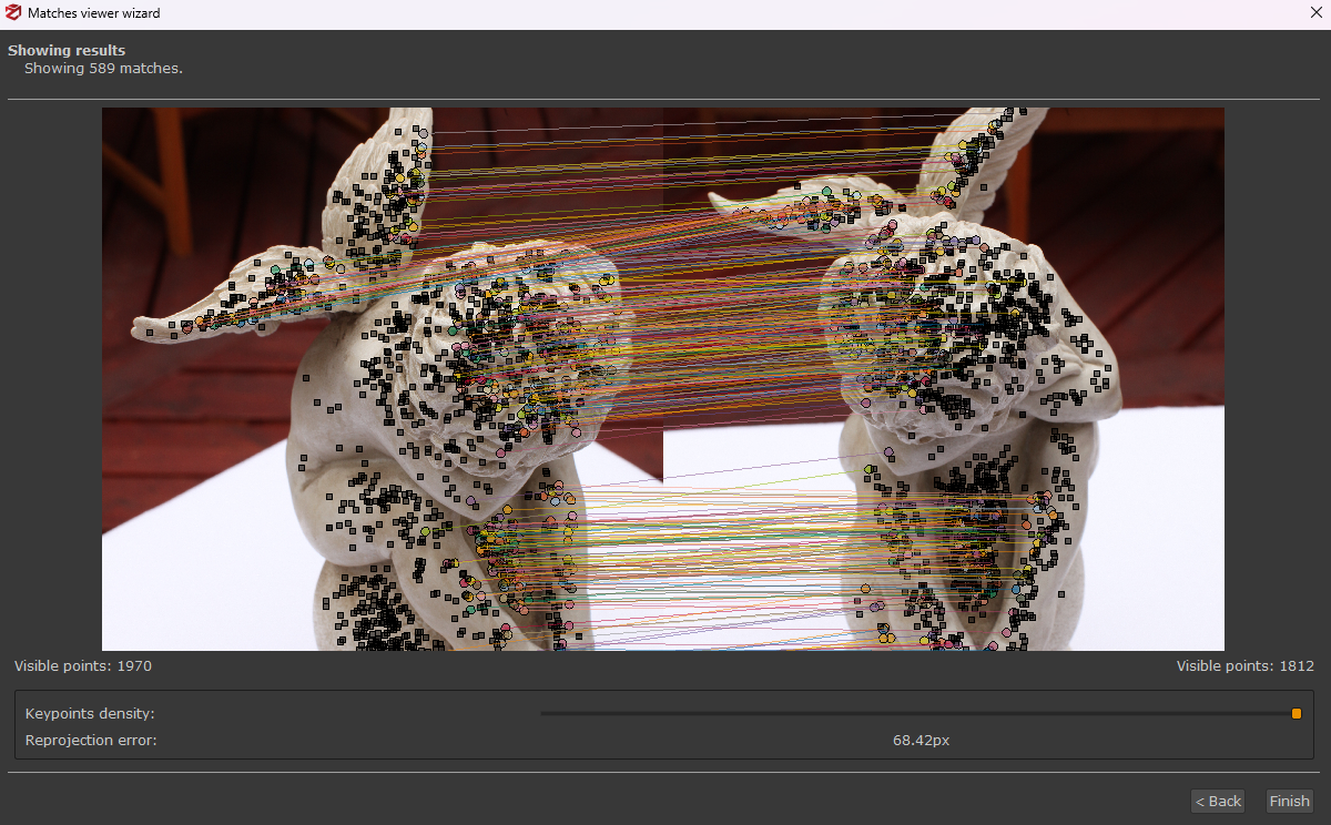
- Matches Viewer: opens the match viewer interface. Simply select an image on the left panel by left-clicking it and similarly an image on the right panel. After clicking "next", keypoints and matches will be shown with a line between the two images. Simply click "back" and repeat the process to see matches from different images.
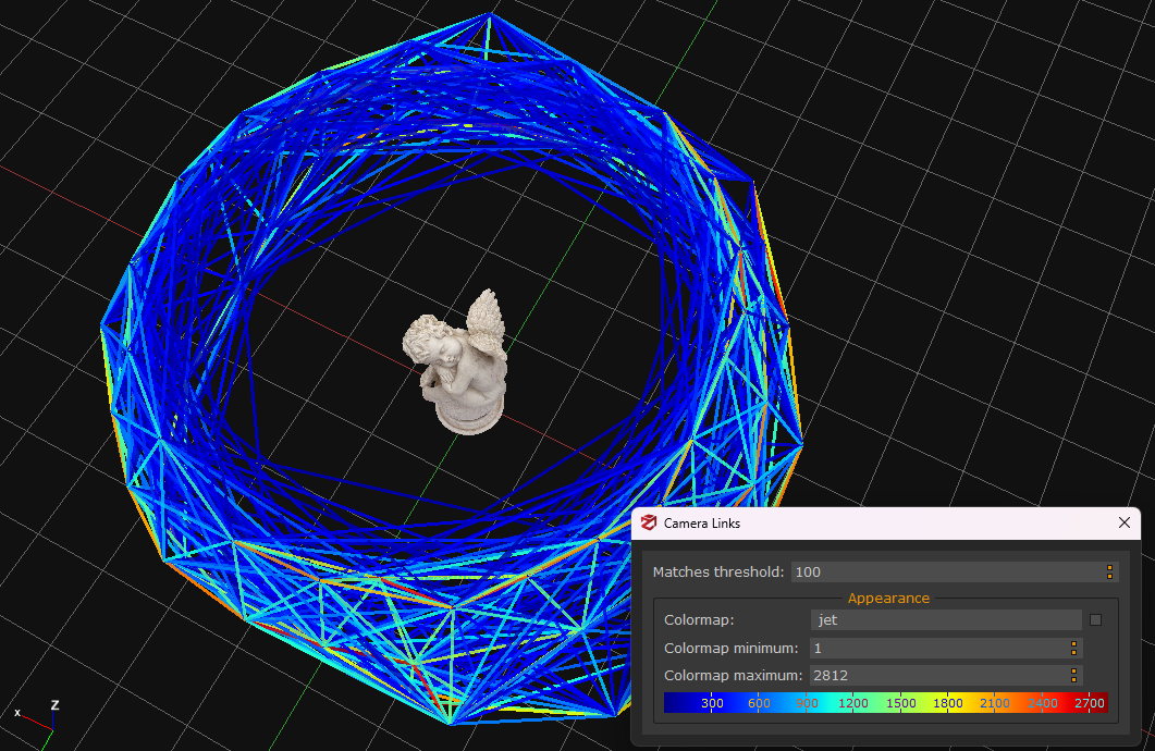
- Camera Links: they show the strength of the matches between the cameras during the orientation phase. A series of lines which link the cameras will be shown in the workspace according to a matching threshold defined by the user, while their degree of intensity is indicated through a color map.
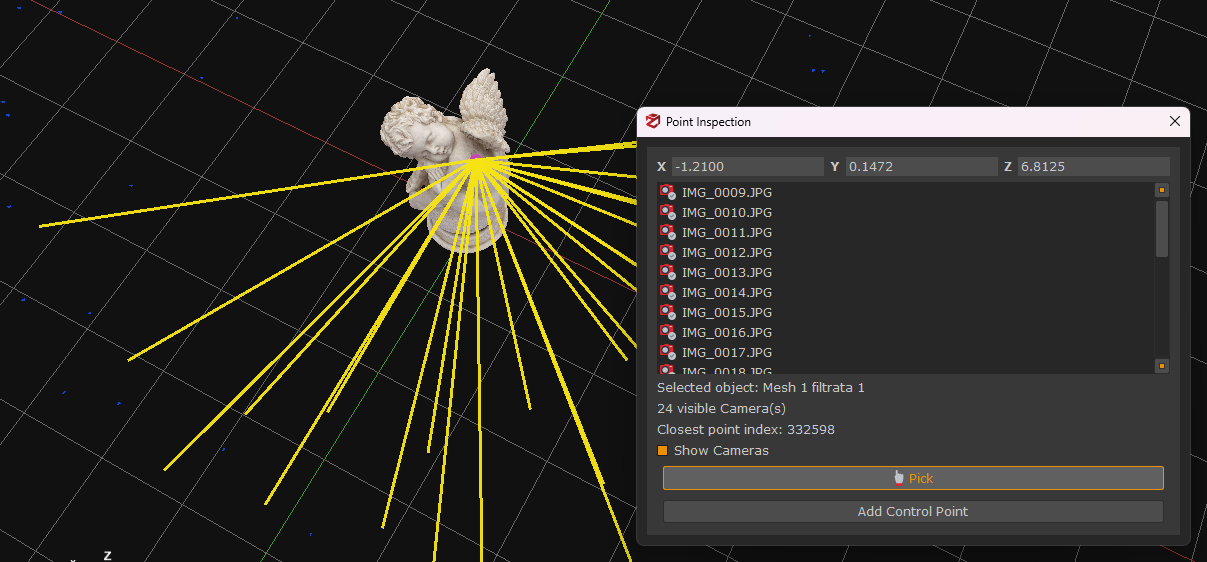
- Point Inspection: this tool enables the user to pick a desired point upon your 3D model. The cameras that see that specific point will be shown in the viewport and listed in the dedicated window, along with its XYZ position in the 3D space.
- Camera GPS Coordinates: shows a preview of the GPS coordinates via OpenStreetMap.
- Enable/Disable Confidence: allows the user to see/hide information about the dense point cloud confidence.
- Optimize camera parameters: this tool allows running a further bundle adjustment, in order to improve the accuracy of the Structure from Motion algorithm. It is advisable to run this tool before running the Multi View Stereo phase (dense point cloud extraction).
Tip: a typical case in which the bundle adjustment step is required is when the first camera orientation step has completed with a mean reprojection error value above 1: after placing at least three control points from the images it is possible to run the "optimize camera parameters" step, giving much more weight to the defined constraints.
- Optimize camera parameters using terrain assumption (experimental)
This tool allows the user to run the bundle adjustment, however by assuming a terrain. This is very useful when the structure from motion suffers from error drifting and causes the reconstruction to look "bent". By using this tool, Zephyr will guide the reconstruction using a planar assumption.
- Manage camera layers: manage multi-layers for multi-layers datasets.