Drawing Elements & Layers
These functions are not available in 3DF Zephyr Lite and 3DF Zephyr Free.
The Free Drawing tool in the "Drawing" section of the Editing tab allows you to draw polylines, splines, surfaces, points, and text directly on the 3D model.
Please note that drawing elements can be exported into DXF, SHP, DNG and XML files.

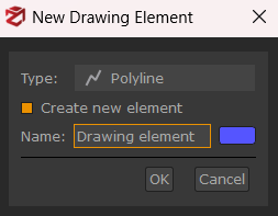
You can choose the drawing element type (polyline, surface, spline, point, text) from the popup dialog, by pressing the  button.
To create a new separate drawing element, the Create new element checkbox must be selected.
It's possible to rename the drawing element and change its color before pressing OK.
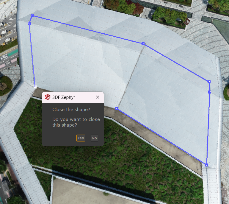
Once you draw a polyline or a spline, you can close the drawing element by clicking on another vertex. A popup window will be asking you if you want to close the drawing element:
By clicking the Edit button  , it's possible to add, relocate, and remove the selected point of a certain polyline, spline or surface. You can also subdivide the polyline by clicking on the Subdivide button
  .
.
Once the Edit button is pressed, it's possible to move the drawing element vertices by pressing the Move button  , or delete them with the Remove button
  .
.
You can also use the Snap function to link the polyline you're currently drawing to another already created: you can do that by using the main vertices ("snaps") of the drawing elements, such as the near/mid/end vertex.

The following modes can support you while placing the polyline/spline/surface points in the 3D workspace:
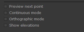
- Preview next point allows to have a preview of a point that has not been placed yet. This mode is handy for splines creation because you can check the curvature trend while placing the points.
- Continuous mode allows for automatically placing multiple points while moving the cursor.
- Orthographic mode allows for switching to the orthographic view during the drawing elements creation.
- Show elevations allows for displaying the elevations of the drawing elements' points.
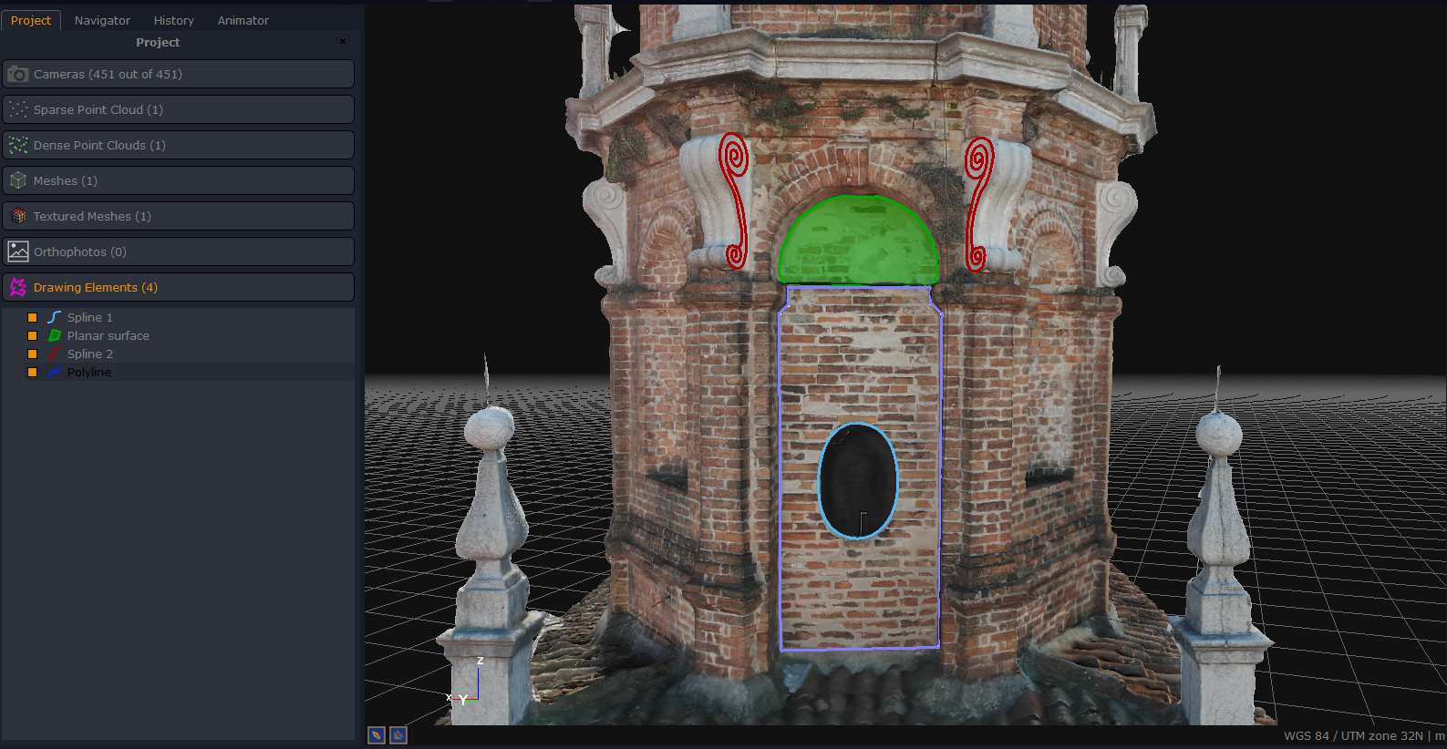
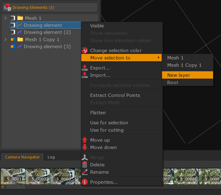
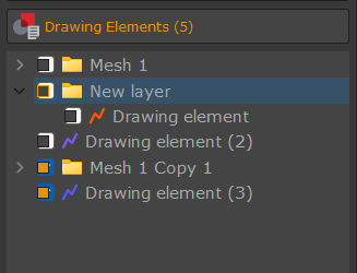
The drawing elements can be grouped into layers regardless of their generation method. In order to do so, you simply have to select the desired drawing element (you may also use multiple selection to move more drawings to the same layer), right click and select the appropriate "move selection to" entry.
Note: the following tools are available after the drawing elements creation:
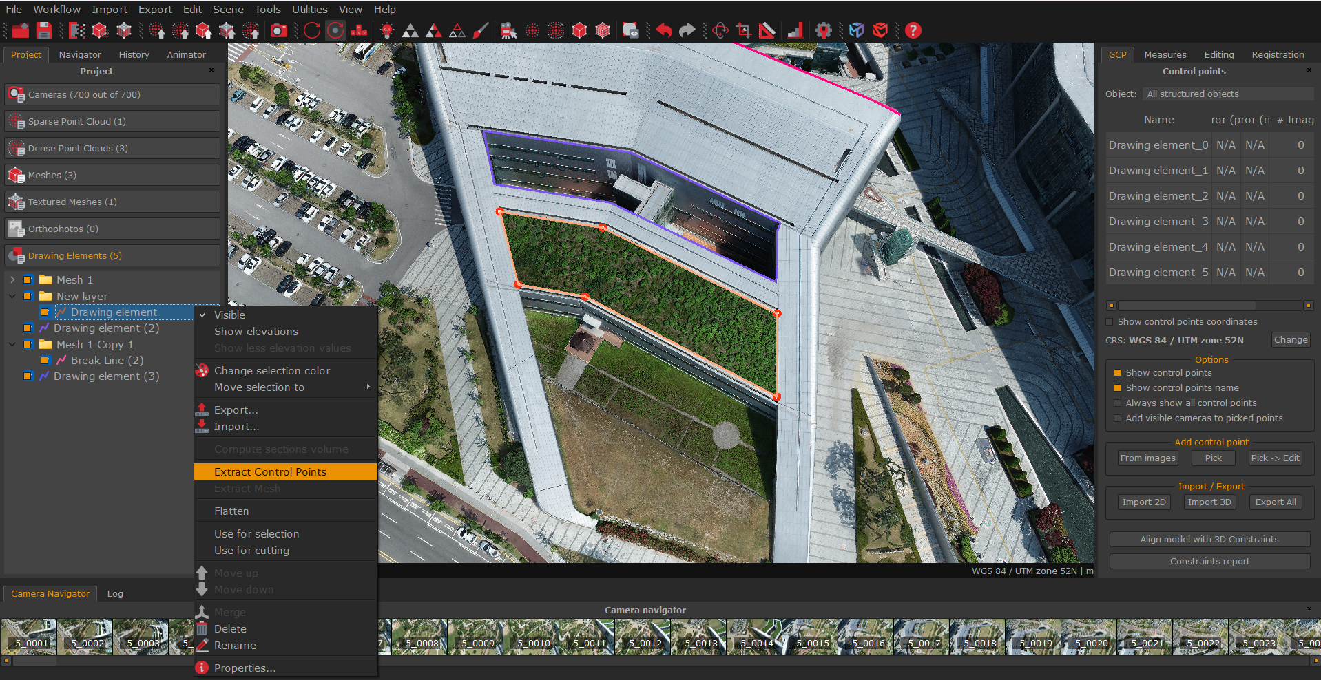
Extract control points - allows creating control points from already placed drawing elements vertices.
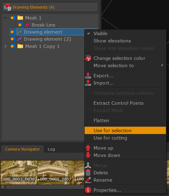
Selection - simply right click on a closed polyline/spline and pick the "use for selection" option to select points or polygons enclosed by the relative polyline/spline.
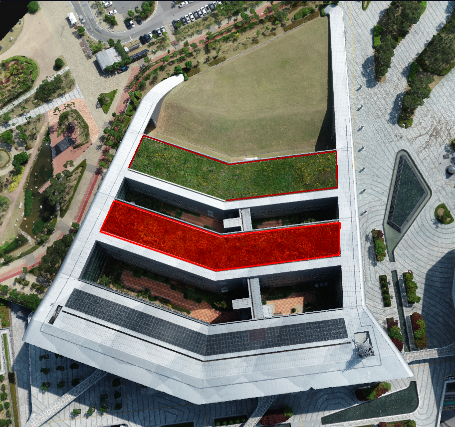
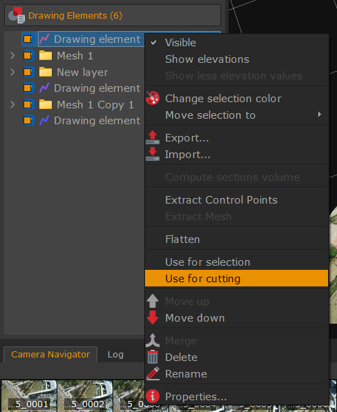
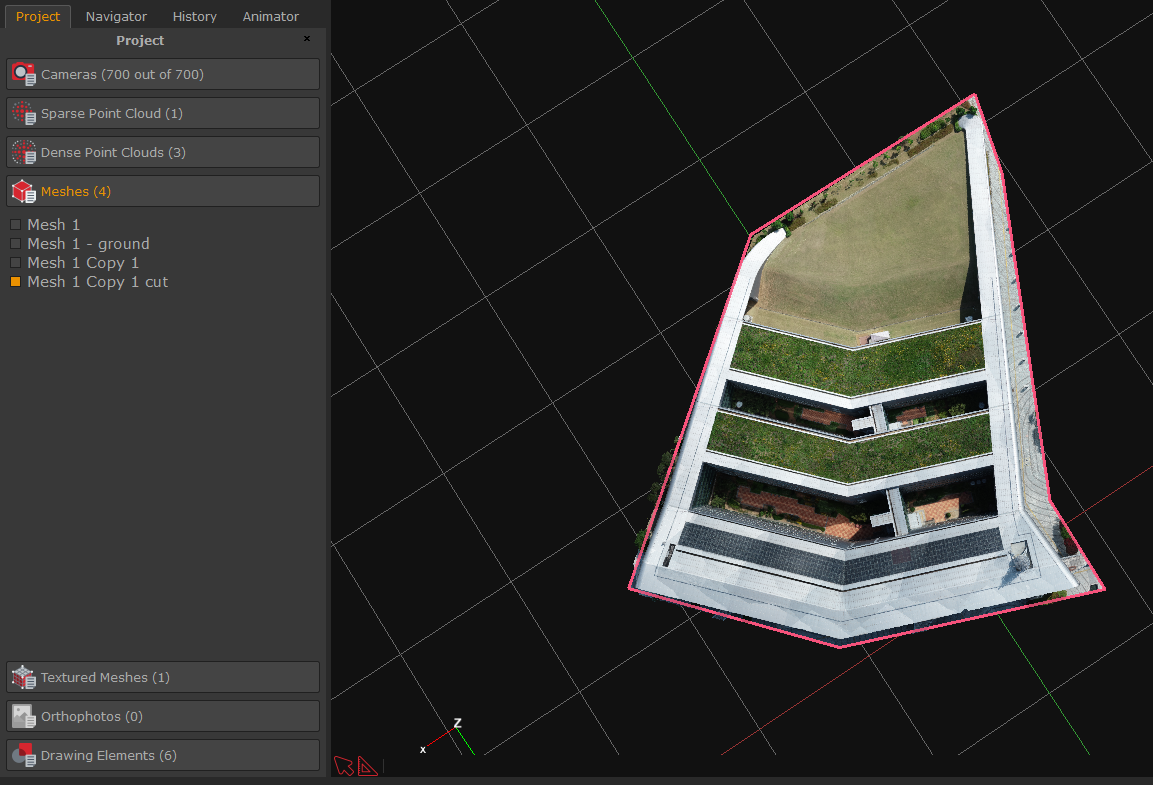
Cutting - right click on a closed polyline/spline and pick the "use for cutting" option to cut the area enclosed by the relative polyline/spline.
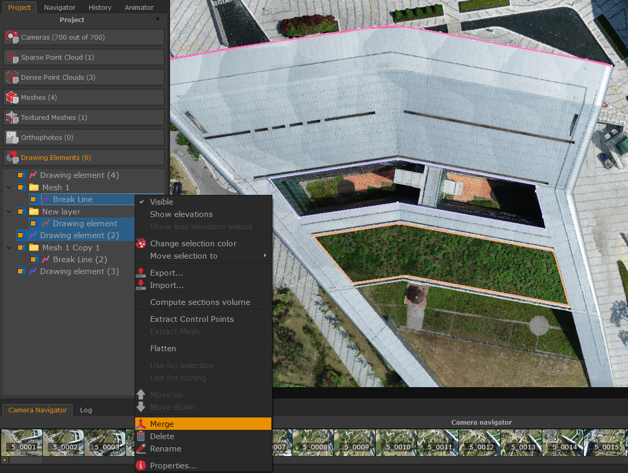
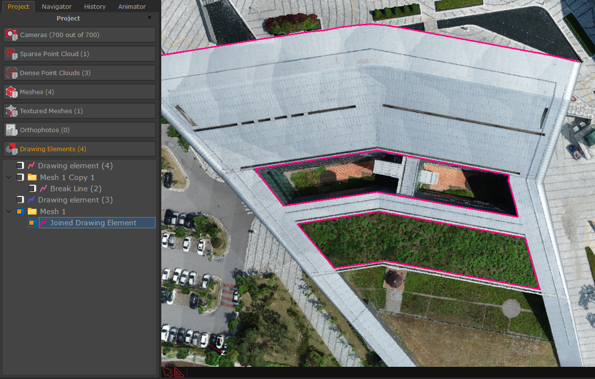
Merge - Allows to combine separate drawing elements of the same type.
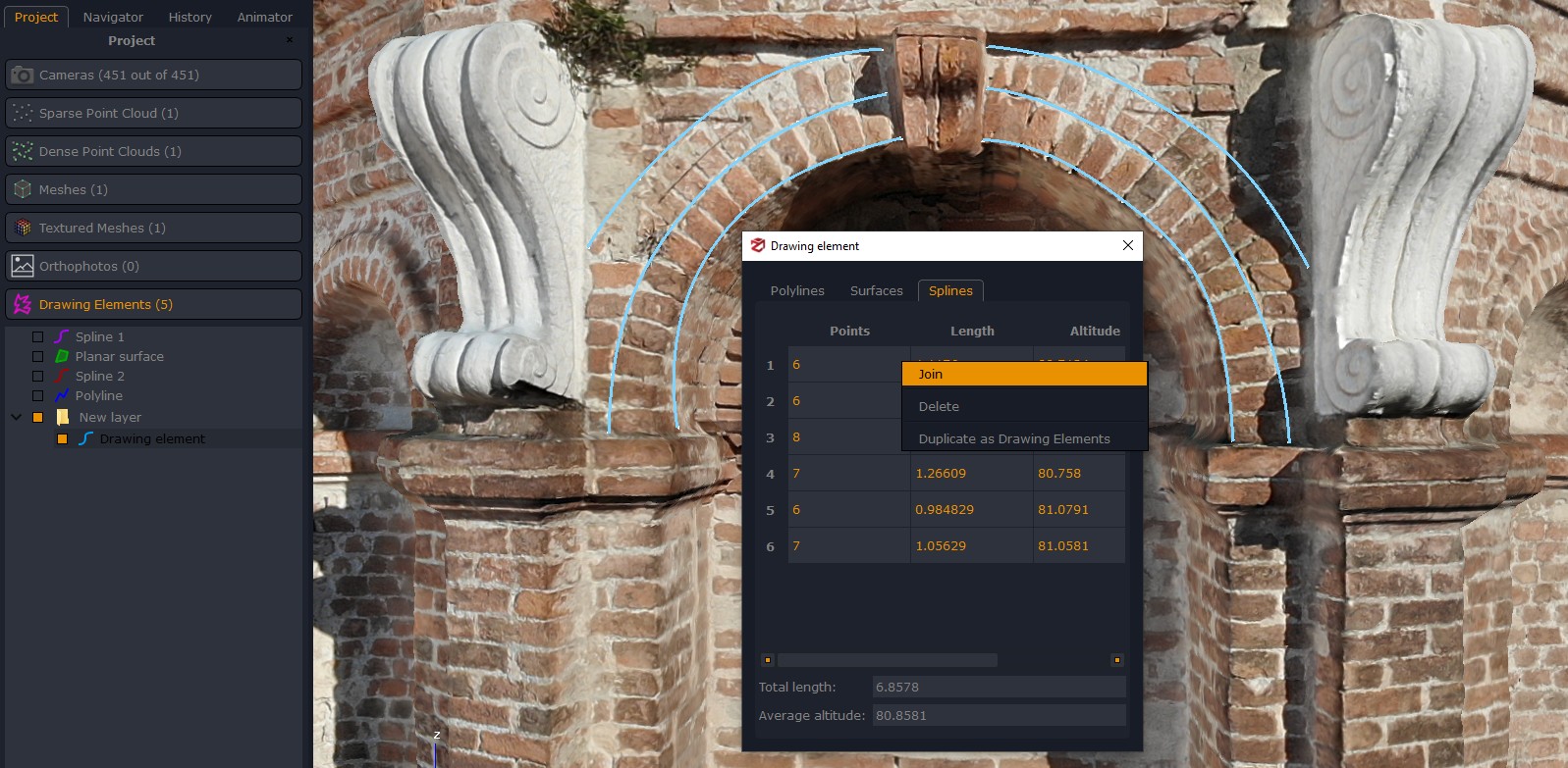
Properties show information about the selected drawing element. Right click on a polyline/spline to choose among Delete, Duplicate as Drawing Elements or Join option.
Please note that you need to select the drawing elements listed in the properties and right click the Join option in order to join them together. Once you are done, the properties will list only one polyline/spline.