Guided BreakLines
To create breaklines, simply click Tools > Lines Extraction > Guided BreakLines Extraction, or select the "Guided BreakLine" option under the Drawing section from the Editing tab.
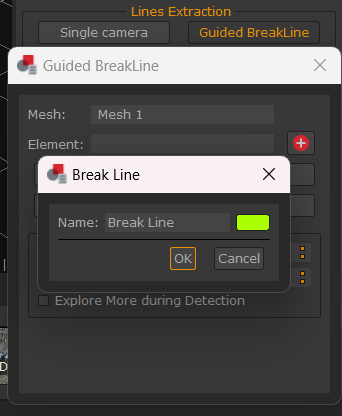
Click the  button in the popup dialog to rename the breakline and/or change its color. Click OK to add the new drawing element to the current workspace.
Breakline creation Settings are as follows:
- Max Segments number: defines the maximum number of the breakline segments to detect.
- Max Angle degree: sets the maximum angle between two segments.
- Explore more during detection: this flag enable a more explorative detection, which helps recognize more extended profiles on the mesh structure. This option increases the amount of calculation conditions of the algorithm in order to find longer and more articulated profiles. You can enable this option if the standard guidance is not good enough. Be aware that drifts are more likely to occur.
Once you draw the first vertex, you will notice the breakline will point to the vertex closest to the mouse cursor while hovering the mesh (guided drawing mode). A preview of the breakline (blue line) will be displayed in the meantime. You have to left-click again to add the breakline.
Drawing can be paused and resumed by clicking the "Pause" and "Continue" buttons, respectively.
You can switch between guided and manual drawing mode anytime by clicking the Free drawing / Guided drawing button.
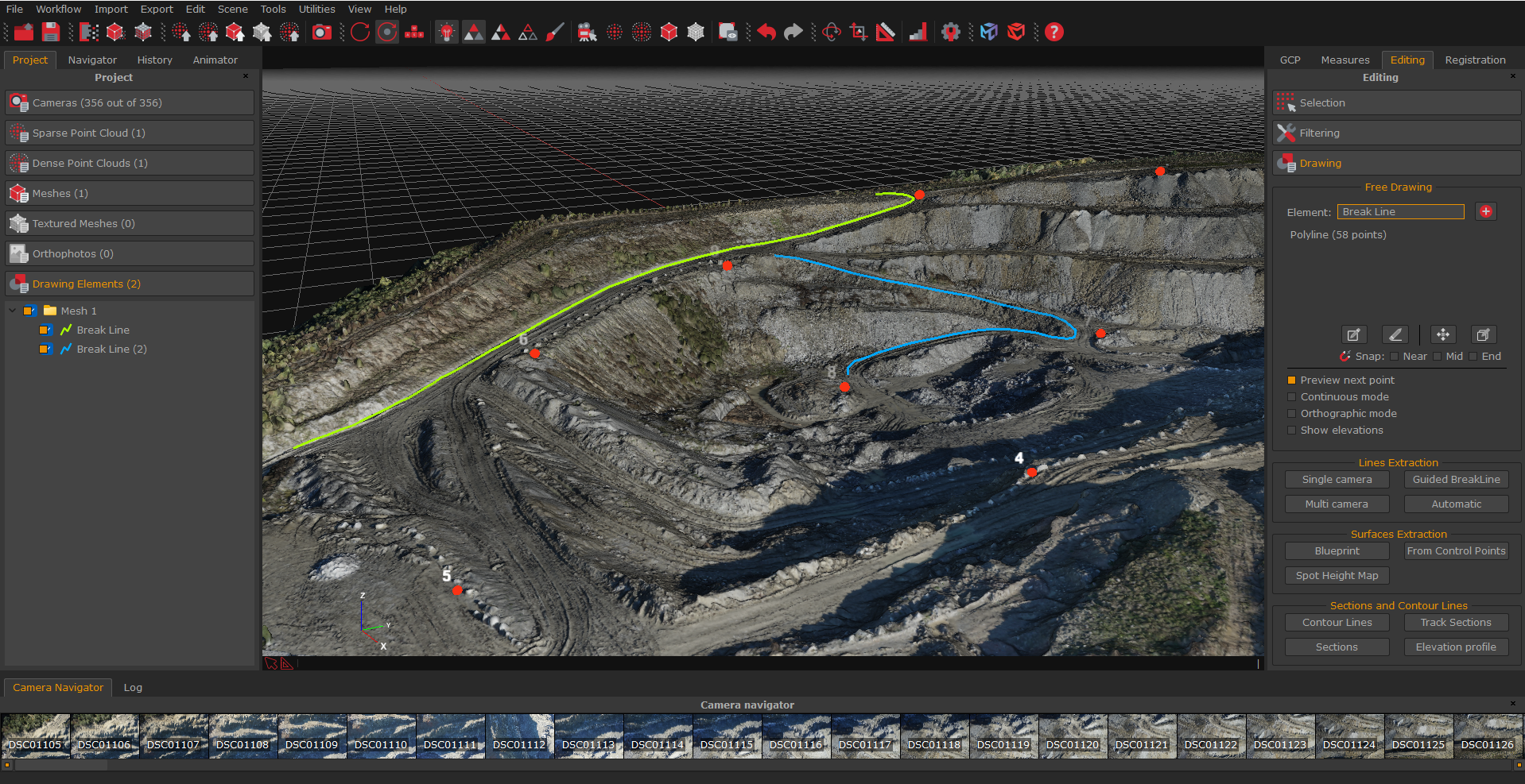
Note: the segments size of the breakline will be similar to the first drawn segment. In this respect, the algorithm behavior is highly influenced by the length of the first segment and it will try to replicate the same length for the successive segments. Therefore, if the searched profile is extended, it's usually recommended to draw a relatively big first segment in order to save time. However, please be aware as the segment size determines the accuracy of the final line.