Project Panel
The Project panel is located in the left sidebar of the main Zephyr interface. This panel gathers the most important parts of the .zep file.
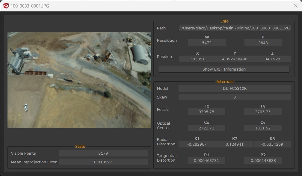
In the Cameras section you can find thumbnails of the images imported in Zephyr, both those that were successfully oriented and those that failed the orientation step. By double-clicking with the left mouse button on a thumbnail the properties window will appear with:
- information about the resolution and the position in the Zephyr coordinates system
- internal calibration parameters
- statistics about the keypoints that Zephyr managed to find during the SfM phase and the mean reprojection error;
By right-clicking one or more pictures it is possible to:
- try again to re-orientate the cameras that have not been orientated
- see the picture as an overlay, by changing the point of view
- see the picture thumbnail at a bigger resolution
- rotate and rename the camera thumbnail
- change the camera picture file
- change the mask linked to the camera
- open the properties window
- export external and internal parameters of the cameras;
- export the undistorted images;
The Sparse Point Cloud, Dense Point Cloud, Meshes and Textured Meshes sections all allow users to access the properties of the reconstructed 3D object (double-click with the left mouse button) which will show:
- statistics about the point cloud/mesh with the total number of points/polygons;
- information about the generation process of the cloud/mesh (settings, running time, Zephyr version, generation date and time);
- detailed data about the reconstruction settings as they can be used in .xml files;
- the log file about the reconstruction phase;
Tip: in the sparse point cloud properties you can find the Mean Square Error which shows the quality of the reprojection in the orientation phase. As a rule of thumb, when this value is lower than 1 then the orientation can be considered valid and you can proceed with further steps. With values higher than 1, you may want to execute the orientation phase again by:
- excluding pictures with a very high reprojection error (you can find that value in the properties of every single camera);
- adding control points on the images, exporting them, and then using them as constraints in the first phase;
By right-clicking the generated sparse point cloud it is possible to:
- rename the sparse point cloud;
- reset the bounding box volume;
- export the sparse point cloud;
- view the sparse point cloud properties;
- Modify the order of elements in the project tab;
By right-clicking the generated dense point cloud it is possible to:
- rename the dense point cloud, clone it or delete it;
- export the dense point cloud;
- see confidence information (3DF Zephyr Pro and 3DF Zephyr Aerial only);
- view the dense point cloud properties;
- Modify the order of elements in the project tab;
By right-clicking the generated mesh it is possible to:
- rename the mesh, clone it or delete it;
- export the mesh;
- compute the mesh volume (this feature is not present in 3DF Zephyr Lite and Free - the value will be saved in the mesh properties);
- view the mesh properties;
- Modify the order of elements in the project tab;
By right-clicking the generated textured mesh it is possible to:
- rename the textured mesh, clone it or delete it;
- export the textured mesh;
- view the textured mesh properties;
The full version of 3DF Zephyr also features the Orthophoto.
By right-clicking a generated Orthophoto it is possible to select the following options:
- Open in DEM Viewer: opens the orthophoto in the DEM viewer;
- Open in Multispectral Viewer: opens the orthophoto in the Multispectral viewier tool;
- Edit: opens the Orthophoto Editor;
- Relocate: allows you to locate the orthophoto to a new pathway;
- Bands: enables viewing the orthophoto according to the selected band;
- Export: opens the orthophoto export tool;
- Rename, Clone, Delete;
- Properties;
The full version of 3DF Zephyr also features the Drawing Elements subsection including sections, contour lines or vector graphics.
By right-clicking a generated drawing element it is possible to:
- rename the drawing element;
- change the color of the drawing element;
- export all the drawing elements or those visible/selected;
- access the drawing element properties;