Control Points panel
These functions are not available in 3DF Zephyr Lite and 3DF Zephyr Free.
Control points allow you to define specific coordinates; that can be used then to calculate the distance between other points and cameras and use them as constraints for the alignment of the point clouds or mesh.
Control points, alignment, and model scaling with known control points (or known distances) can be managed from the panel on the right labeled GCP (Ground Control Points), where the GCP created or imported in 3DF Zephyr will be listed with their information.
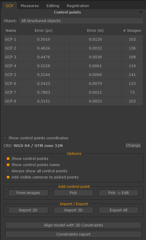
Coordinates Reference System (CRS) section
This section will display the current reference system used. It can be changed by clicking the "Change" button and opening the Change current coordinate reference system window.
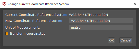
Clicking on the "Select Projection CS" option in the New Coordinates Reference System drop-down menu, will open the Projection Coordinates System window:
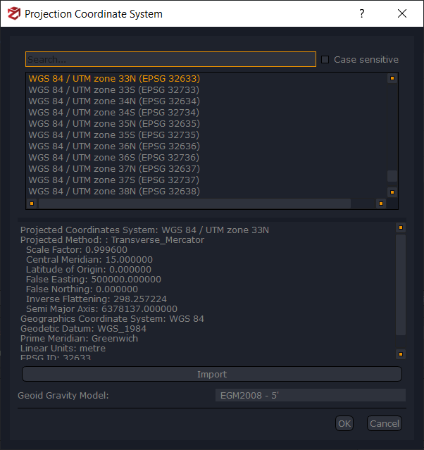
Select the new correct coordinate reference system from the 3DF Zephyr database, or import a new one from an external source by clicking the "Import" button, and click "OK".
Optionally, a Geoid Gravity Model can be loaded as well, in relation to the Coordinate Reference System. This feature can be helpful if you have taken GPS coordinates in a different reference system, which will cause a wide metric error compared to the GPS coordinates obtained from the pictures.
To complete the reference system's change, be sure that the "Transform coordinates" flag is checked, and click "OK" in the previous window.
Add control point section
These functions will allow the placement and movement of the GCPs in the project.
- "From images" Function: Allow to add control points by picking on photos.
A much more accurate way to add control points is to pick them directly from the photos. You need to pick the same coordinate on at least two pictures in order to triangulate and make Zephyr calculate the control points.
If necessary, it's possible to clear all previously created control points by right-clicking on the point list and left-clicking "Delete All",and "Yes" to confirm. Each control point can also be removed individually by right-clicking on the appropriate row and clicking "Delete".
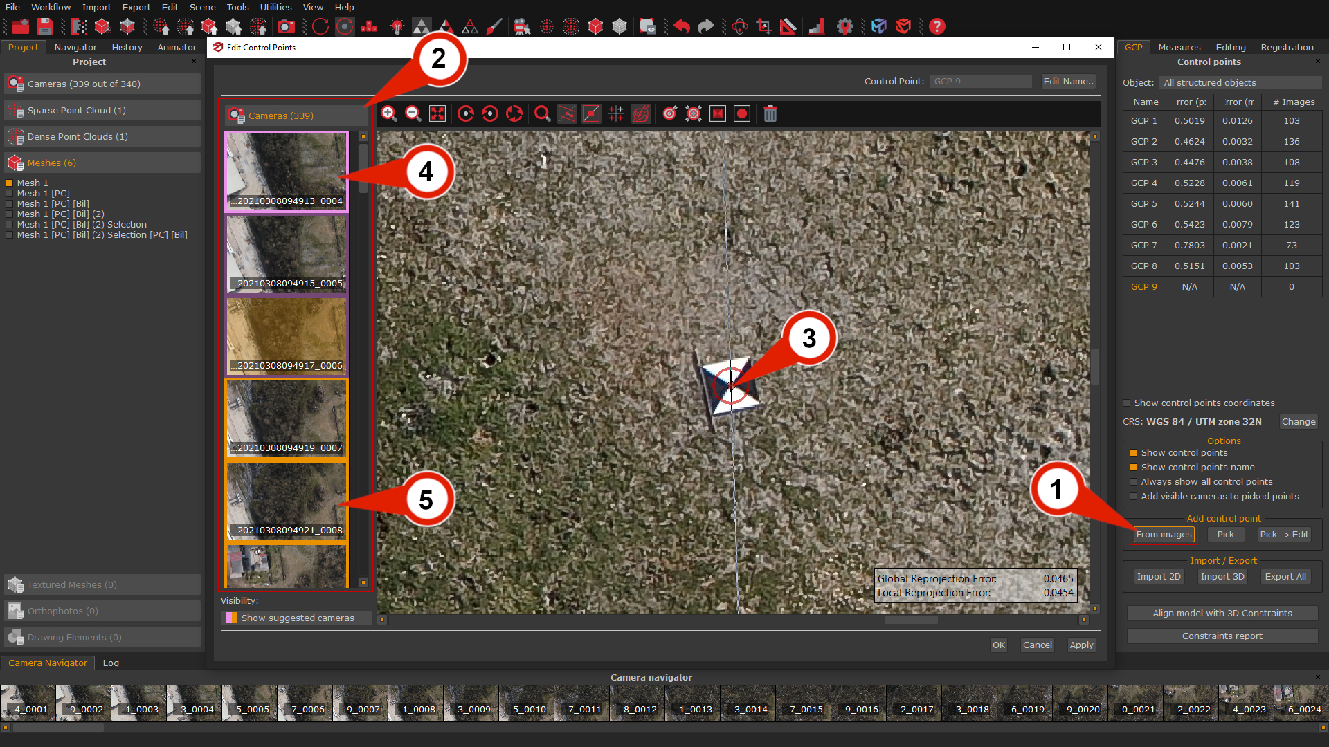
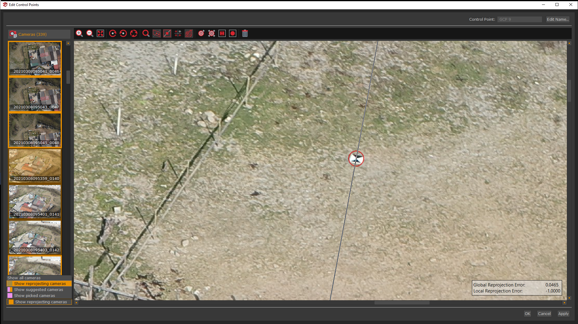
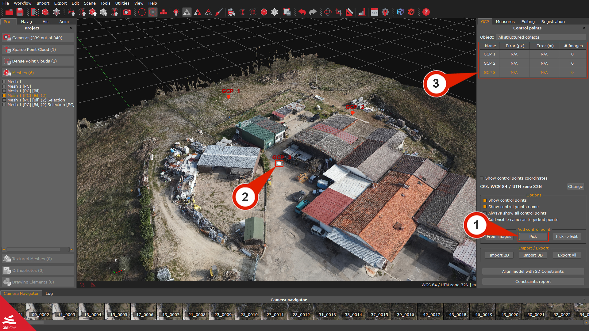
From the GCP panel, in the Add control point section, click the "From images” (1) button: the Edit Control Points window will appear.
In the Camera list (2), left-click a picture to view it in the Control Point Picker Selector.
Left-click where you want the control point, and an Red dot (3) will appear. A violet border will highlight the first selected image (4), but the "OK" button won't be available yet: remember, at least two images to define a control point in the 3D space are needed.
Click on another image in the camera list (2): this time the epipolar line will also appear (highlighted by the color inversion in the picture), which will help to position the second 2D coordinate by left-clicking, the available images will be highlighted by a yellow border (5). It's possible to add as many coordinates as wanted (usually, the more coordinates the better the accuracy) and click "OK" to complete the control point selection.
As the positions of the selected 2D points are changed, you can see the Global Reprojection Error and Local Reprojection Error of the control point in real time.
The Advanced Tools can provide valuable help with control point placement in the editing window:
|
Advanced Tools |
|
|
Fit in view: resize the image to fit in the view. |
|
|
Rotate 90 degrees clockwise, counter-clockwise, reset rotation: rotate the image and reset the initial position. |
|
|
Show magnifier: show/hide the magnifier on the cursor while placing control points on images. |
|
|
Show reprojection error: show/hide local and global reprojection errors of the current control point. |
|
|
Show epipolar line: show/hide the epipolar line. |
|
|
Show other points: show/hide previously placed control points. |
|
|
Automatic matching on current image: automatically find and place a control point on the current image. |
|
|
Automatic matching on all images: automatically find and place a control point on all the pictures |
|
|
Detect marker: It automatically detects the center of a rectangular marker placed in the scene. By clicking the "Detect marker" icon and drawing a rectangle upon the center of the marker you want to be found, 3DF Zephyr will automatically place the control point at the center. Note: Using the tool with a check-board style marker will improve the automatic detection. |
|
|
Detect sphere: it allows to detect the center of the spheres placed in the scene. By clicking on the "Detect sphere'" icon and drawing a rectangle over the sphere you want to be found in the image, 3DF Zephyr will automatically place the control point at the center. Note: This feature is expressly designed for the forensics industry, i.e., to support the analysis of the line of fire in crime scenes where a laser scanner scans the spheres on the trajectory rod. |
|
|
Clear point: remove control points placed on the image. |


You can change the camera "Visibility" by selecting the "Show reprojection cameras" option from the drop-down menu in the bottom left corner of the editing window, that's filter will permit to place the control points on "far cameras" (dull yellow frames) as well. In some cases, this method could improve the accuracy, especially when a few cameras come with and a high reprojection error. The"Show picked cameras" option will shows cameras (violet frames) where the control point is already placed.
- The "Pick" Function: allows to add control points by direct picking in the rendering window and it's the easiest way (albeit the least accurate) to insert a new control point from the 3D reconstruction directly.
From the "GCP" panel go to the "Add control point" section and click the "Pick" (1) button. The mouse cursor will be displayed as crosshair icon (+): move it on the scene and left-click (2) the desired control point position. A new control point will be added to the control points list (3) and will be automatically shown in the scene.
Note: This control point selection mode cannot be done on a textured mesh.
- "Pick → Edit" function
From the same section Add control point, it is also possible to find the "Pick → Edit" button: this function allows the user to select a control point by directly picking it on the scene (exactly like the "Pick" function) and then modify the position of the control point by editing its position with the "add control point from images" interface, with the control point already in place in all the possible cameras.
Import / Export section
In this panel section will be possible to import control points from a text or csv files.
- The "Import 2D" function
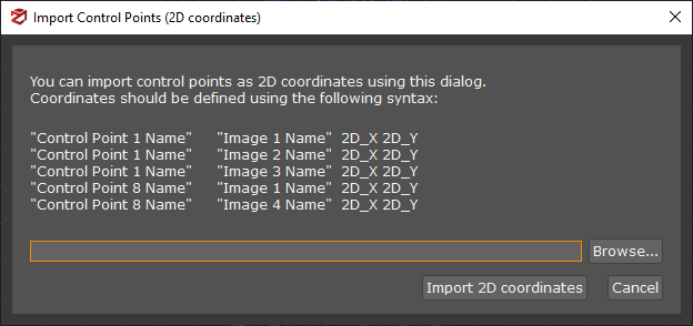
Importing control points from text files allows the user to add control points exported from 3DF Zephyr, or other applications automatically: to do that, click on the "import 2D" button, pick the desired text file and then click "Open". A window will appear to confirm that the import phase has been completed successfully: click "OK".
Example:for each imported control point, it is necessary to define coordinates for at least two images. For example, to import a control point named "Point1" seen by the camera "PictureA.jpg" at the (x,y) coordinates 100,600 and from a second camera "PictureB.jpg" with coordinates (x,y) 200,660, the file has to be formatted in the following way:
Point1 PictureA.JPG 100 600
Point1 PictureB.JPG 200 660
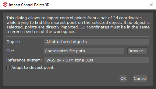
- The "Import 3D" function
This tool allows the user to define control points by using 3D coordinates directly, without detecting any control points in images. In order to exploit this tool the 3D coordinates must have the same reference system as the workspace where the 3D model is being processed. Afterwards control points can be defined for each 2D coordinate as needed.
It is necessary to specify a reference object if users want to get the metric error between their model/cloud and the 3D coordinates.
- The "Export All" function
Next to the "Import 3D" button it is possible to access the control point (and distances, defined in the "Measures" tab) export function.
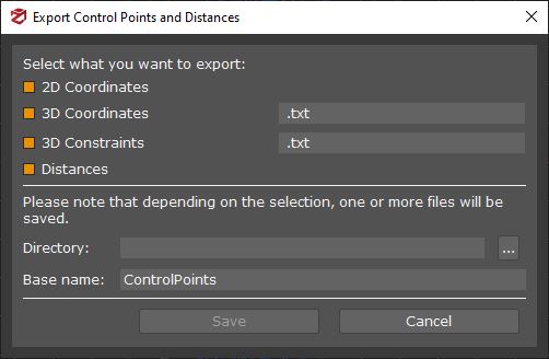
From this window it is possible to export:
- 2D coordinates
It creates a *ControlPoints2D.txt file - it defines the control points as 2D images coordinates, as:
"Control_Point_1" "IMG_3319.jpg" 4.33473658e+03 2.24061730e+03
"Control_Point_1" "IMG_3320.jpg" 3.30352087e+03 2.42468881e+03
"Control_Point_2" "IMG_3319.jpg" 3.01642756e+03 3.16114630e+03
"Control_Point_2" "IMG_3320.jpg" 1.68567672e+03 2.14786953e+03
- 3D Coordinates and 3D Constraints
It creates a *ControlPoints3D.txt\ .scr\ .dxf\ .ncn files - it defines the control points as 3D coordinates, as:
"Control_Point_1" 8.18880729e-01 -5.14516149e-01 4.54143586e-01
"Control_Point _2" -5.64690812e-01 -5.65085273e-01 1.09244112e+00
- Distances
It creates *ControlPoints_Dist.txt file - it defines the distances as seen in the measurements tab, as:
"Control_Point_2" "Control_Point_1" 2.33824531e+01
- The "Align model with 3D Constraints" tool
This feature is similar to the Import Constraints page when creating a new project in 3DF Zephyr. It allows you to scale and georeference your project after creating a sparse point cloud using cameras, constraints, or control distances.
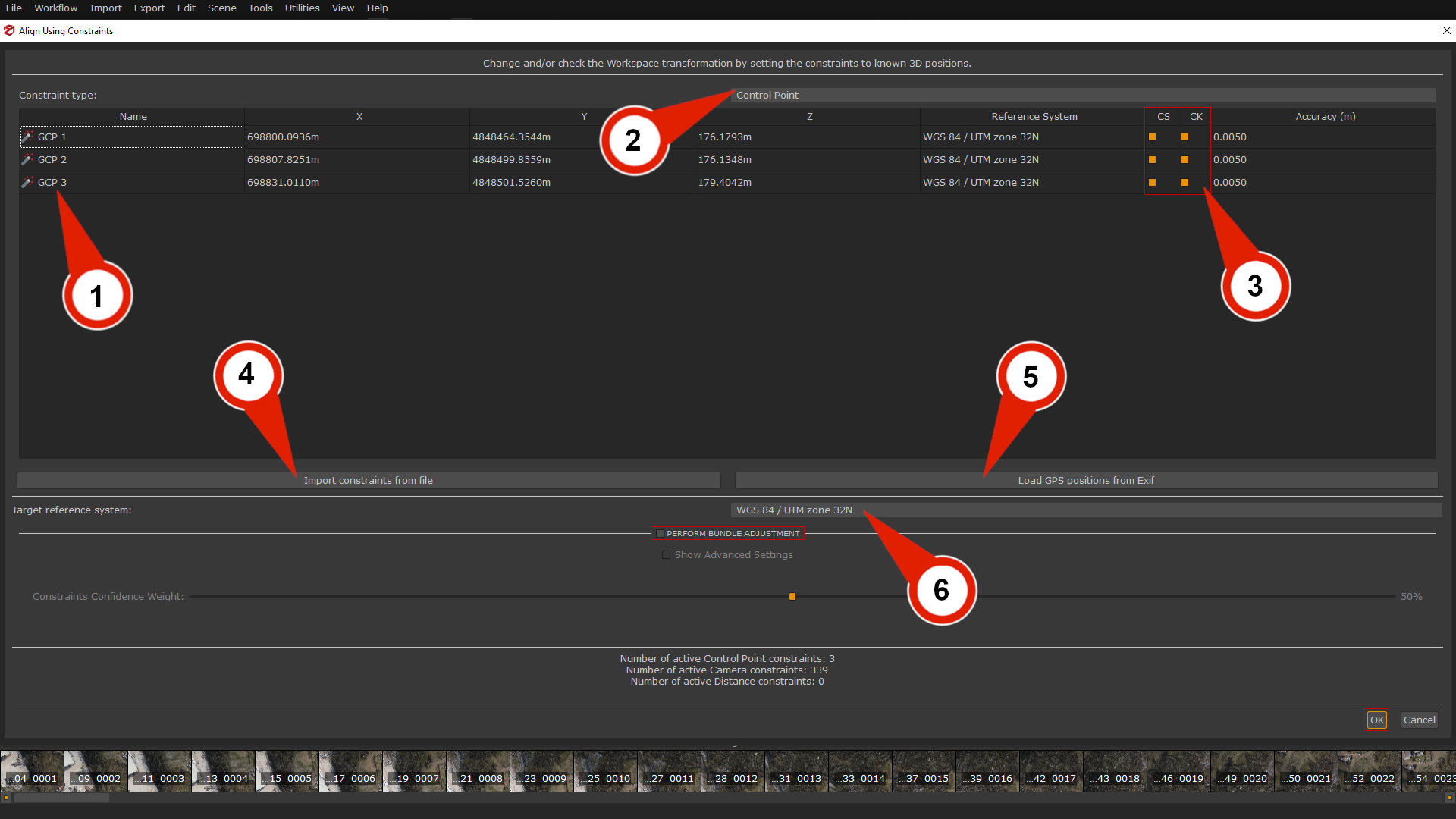
After defining at least three constraints (1) in the GCP Panel, you can scale the model by using them individually or together with image positions or control distances.
Changing the Constraint type filter (2) to:
- Camera option will allow viewing each image's GPS coordinates.
- Control point option will allow viewing the imported constraints from an external source.
- Control distances option will allow viewing the distances created in the Measures panel.
Pressing "CTRL+A" will allow selecting all the tab rows, and "Right-click" with the cursor will allow you to Change Reference system and Accuracy for each camera or control point.
Constraints and Check Points column (3)
Each control point can be set as Checkpoint (to measure the residuals), Constraint (used in the bundle adjustment), or both by using the check-boxes on the left of each point. It's always a good idea to include some checkpoints that are not set as constraints.
- Constraints (CS) are those points you are most confident of in terms of accuracy level, and 3DF Zephyr relies on them to drive the scaling process.
- Checkpoints (CK) are references that the software only considers while scaling to monitor the error value.
Example:
Let's think about an aerial survey where you have both coordinates taken using the drone's GPS system and coordinates taken on the ground with a total station for instance. Once you have placed your points in 3DF Zephyr, you can choose which points must be the constraints, namely the points you are confident (of their accuracy) the most, and which points will be taken into account as simple references to keep the error value monitored.
Import constraints from a file button (4):
this function allows directly set constraints from a text or .csv file via the "Import constraints from file" button; the imported coordinates and the GCPs you have added to the project must have the same name/label.
Coordinates should be defined using the following syntax:
"Control_Point_1" 8.18880729e-01 -5.14516149e-01 4.54143586e-01
"Control_Point _2" -5.64690812e-01 -5.65085273e-01 1.09244112e+00
.
Load GPS position from Exif button (5):
This button import camera positions by loading them from Exif information and using them as constraints.
A common scenario is when loading information from images taken by drones or UAV systems that record the GPS coordinates of the shots in Exif data.
It's possible to change the Target reference system (6), in a similar way seen in the GCP tab.
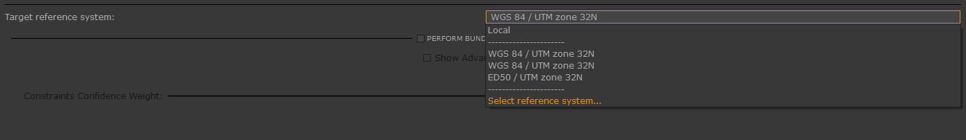
Clicking on "Select reference system" will open the "Projection Coordinate System" window:
You can select the suitable coordinate system from the 3DF Zephyr database, or import a new one from an external source by clicking the "Import" button.
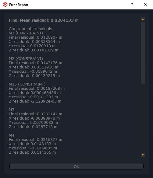
Once the correct reference system has been set, you may also perform the Bundle Adjustment by checking the "Perform bundle adjustment" option. This can be done by using a slider that will assign a confidence weight in the defined constraints and an advanced mode option.
Click the "OK" button to start the scaling process, and an Error report will automatically appear when it is finished. If you need to find and save the report, you can go to the menu: Tools > Control Points > Show Alignment Info.
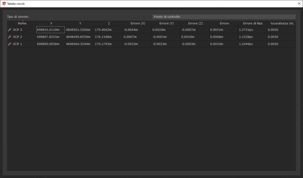
Constraints Report
This button will open a summary window to display all constraints with their positions, errors and accuracy values.