Editing panel
The editing panel allows to access the Selection/Editing tools, Filtering tools and the drawing tools (this last function is not available in 3DF Zephyr Lite and 3DF Zephyr Free).
- Selection/editing tools
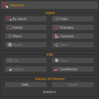
These functions allow to select elements from the workspaces so that they can be edited/managed directly in 3DF Zephyr:
- the manual selection allows to select points (for sparse clouds and dense clouds) or triangles (for mesh and textured mesh) through different selection modes (rectangle, polygon, ellipse, lasso, box). By selecting the desired mode and the desired elements in the 3D space, it will be possible to combine selected elements using the appropriate action (add, remove and eventually by using pause to freely move in the workspace). Those elements will be highlighted in red - once selected, it will be possible to manage them using the appropriate commands in the "Edit" section.
- the selection by color will be applied similarly to both points and triangles: given a certain color (that can be added manually or by picking it directly on the target object from the 3D workspace) all points within a certain threshold will be selected.
- the selection by plane allows to select all elements above (or below) a certain user defined plane.
- the selection by points allow to select all those points (from sparse or dense clouds) that are within the search parameters. The search parameters vary depending on the selected algorithm between:
- Visible cameras;
- Reprojection error;
- X84 Statistic: this algorithm selects those points whose density doesn't meet the X84 statistic criteria. It calculates which are the nearest points or not useful to remove those too far from the correct solution, e.g. the points describing the sky;
- Main plane fitting: this algorithm selects those points which lie well on a plane. It fits a plane using the desired point cloud (decimated due to pc performance). It selects those points whose distance from this fitted plane is under a certain threshold;
- Cloth simulation: it selects those points that according to this algorithm "Cloth Simulation Filter (see http://ramm.bnu.edu.cn/projects/CSF/) appear to be terrain.
- the selection by triangle, similarly to the previous point, allows to select all those triangle within the search parameters depending on the selected algorithm between: longest edge, area, connected components (this last one is very useful to quickly remove all the "floating" noise from the reconstruction).
- the camera selection allows to select cameras directly in 3D space.
Once elements have been selected, it is possible to handle them using the editing tools:
- delete: deletes the select elements from the workspace
- invert: inverts the selection from the workspace
- cut: create a new element by removing the selected elements from the current element
- copy: create a new element by copying the elements from the current element.
- selection: allows to apply a filter only on the selected elements (smoothing, bilateral filtering, retopology).
- confidence: allows to select (and eventually, remove) all the points below a certain confidence threshold.
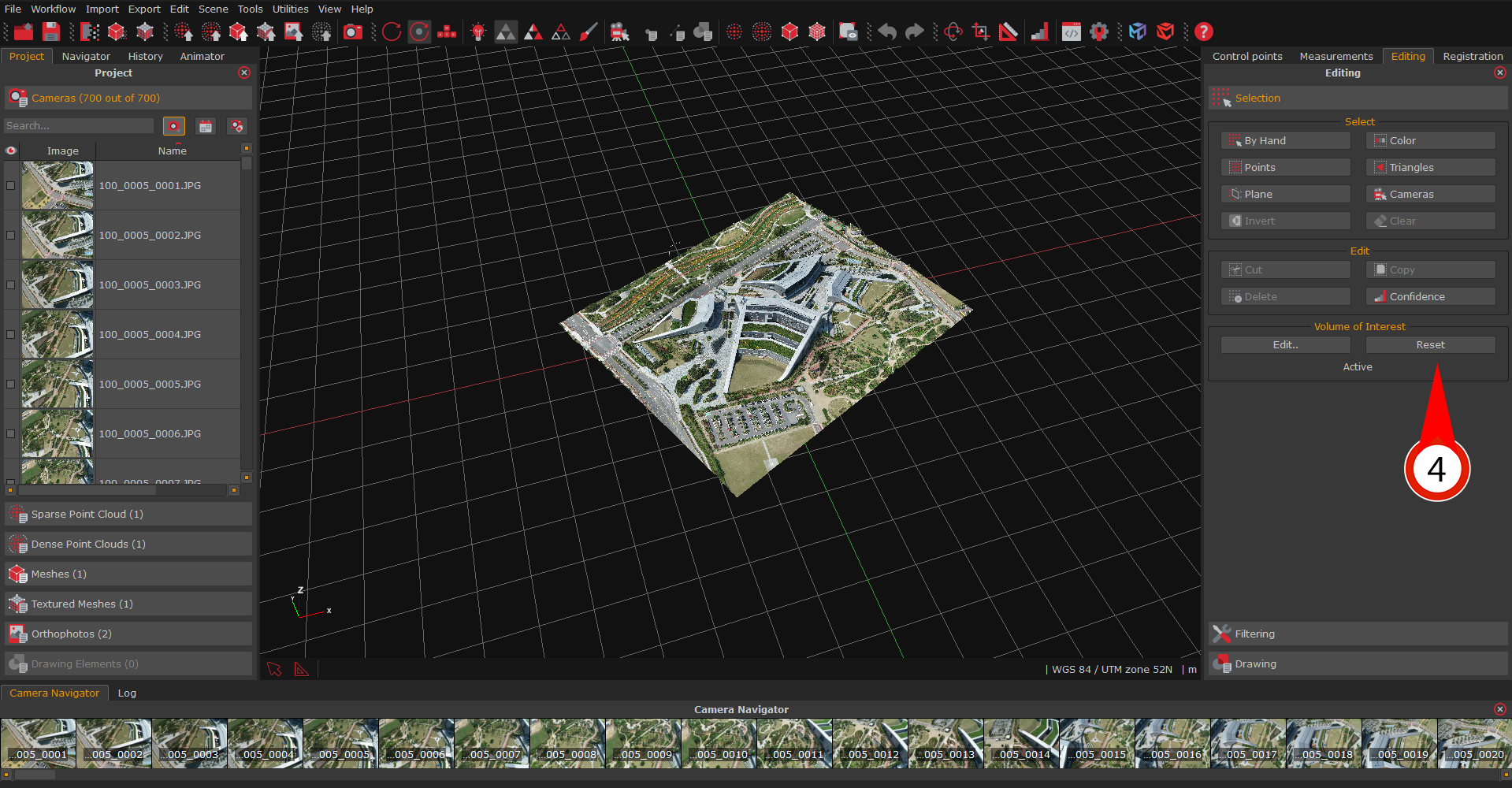
- Volume of Interest
As of version 6.0, the Volume of Interest (VoI) is a new experimental feature designed to aid users during the visualization and editing of huge datasets.
The user specifies a three-dimensional clipping region by visually editing it (this tool works very similar to the bounding box editing tool).
The Volume of Interest tool is located in the Editing panel and you can click the Edit button (1) to enable it and open the "Edit rendering volume" window (2).
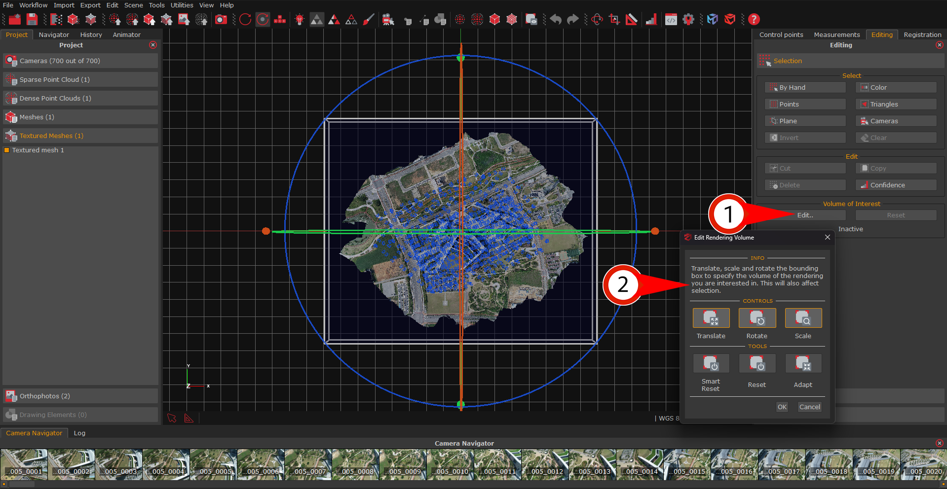
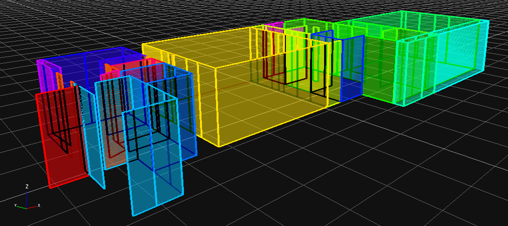
The clipped area will be highlighted by a pink and black waving layer. Once you are done with editing the volume, simply click the OK button (3).
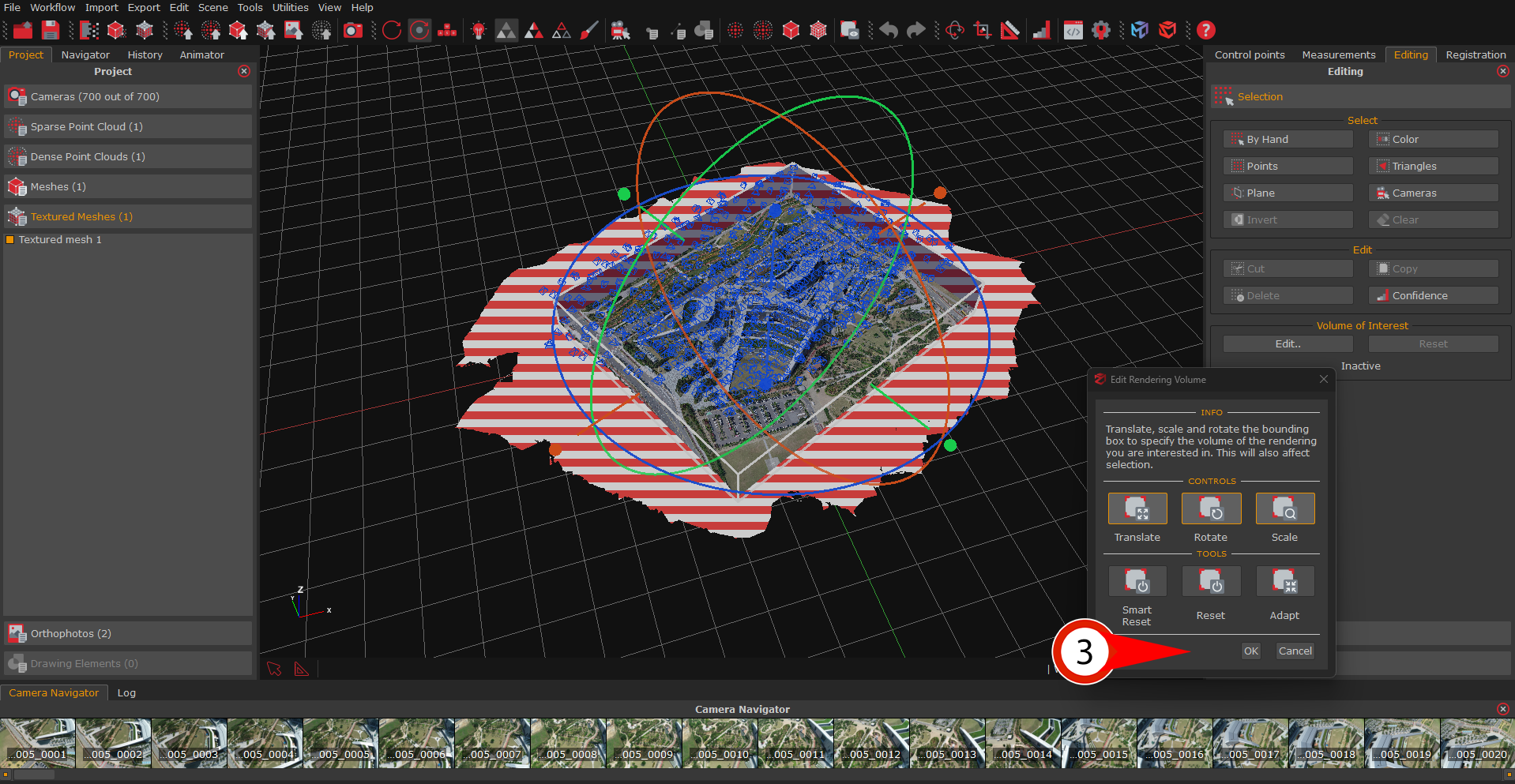
The point cloud/mesh will be trimmed in terms of rendering only, and the user will be free to leverage other tools while the VoI is running (i.e., sections, contour lines or the orthophoto generation can be performed).
Simply click the Reset button (4) to let Zephyr render the original 3D model.
- Filtering tools
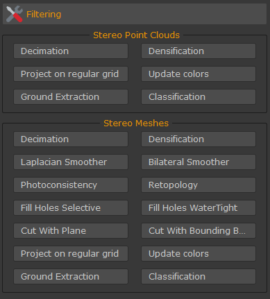
These filters affecting both point clouds and meshes are also available in the Tools menu. You can learn more about these function in the point cloud filters chapter and in the mesh filters chapter.
- Drawing elements tools
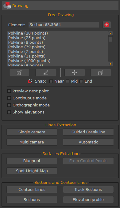
This panel includes the four CAD-dedicated tools available in 3DF Zephyr: the free drawing, the lines and surfaces extraction, and the sections, contour lines and elevation profile generation.
To create a new drawing element, simply click the "+" button - the new element will be automatically added to the "Drawing Elements" section in the Project tab.
Once an element has been created, the drop-down menu to select the current drawing element will be enabled (in this case, it will be shown the only drawing element available, the "Drawing Element" right under the "Create new element" button). This allows you to select and edit previously created drawing elements.
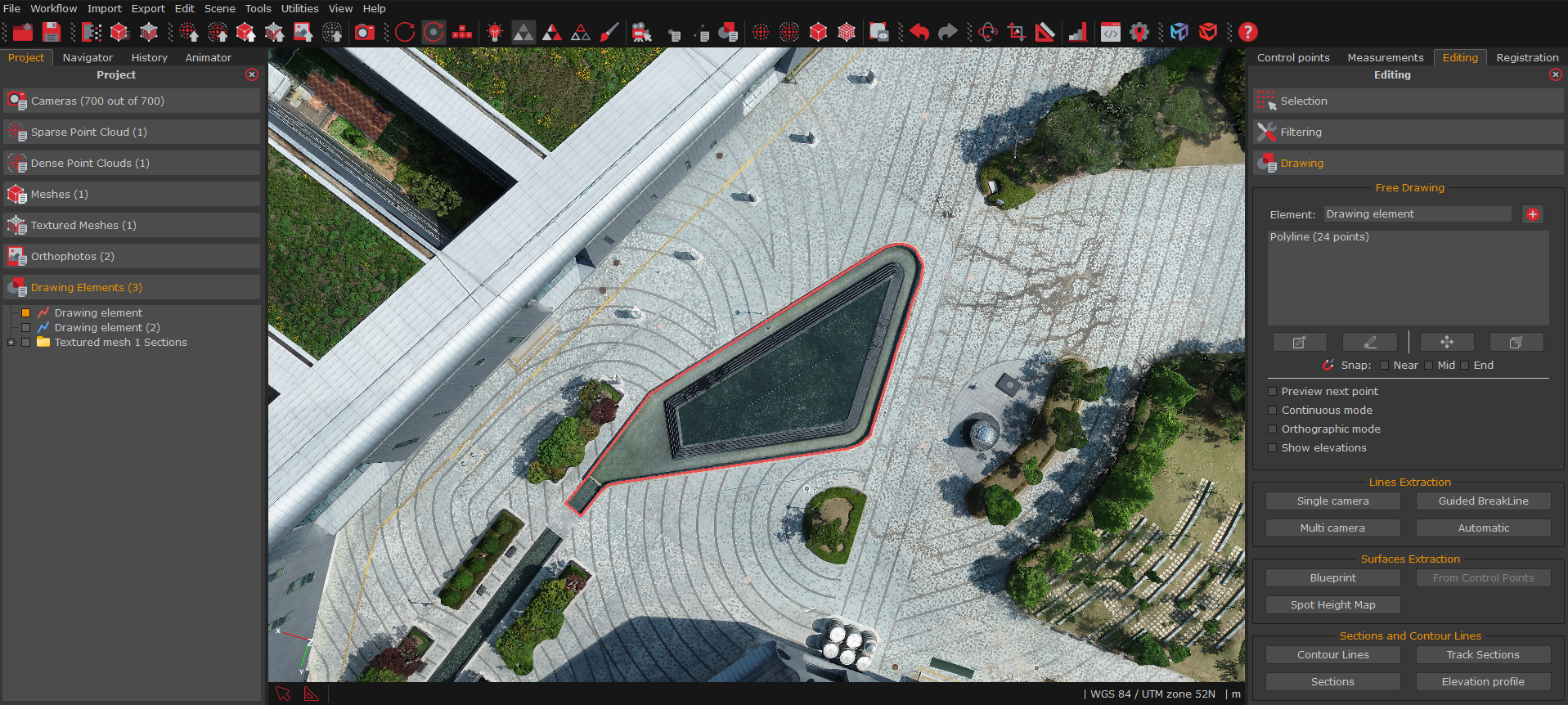
When the drawing element has been selected, it is possible to navigate the scene to the desired position (eventually by making use of the "Orthographic mode" checkbox).
When ready, it is possible to select the middle points that will define the shape of the drawn element, by picking them directly on the mesh using the "Pick" button. You may also use the "continuous mode" checkbox that won't ask for many clicks (each for every middle point) but instead it will draw the line as long as the left click is kept pressed and the cursor is on top of the mesh.
Press "ESC" to exit the drawing mode.
You can change the color of one (or more) drawing elements by selecting and right-clicking the desired element(s) from the "Drawing Elements" section in the Project tab and selecting the "Change selection color" option.
It is also possible to generate a polyline from control points: simply right click a control point and select "Make a polyline". You will be then be able to select the points of the polyline.
Similarly, you can also create surfaces from this very same tool, and again, you can create them also by using control points.
3DF Zephyr also allows to automatically generate blueprints. This functionality works better with laser scanner imported point clouds but can be used also with photogrammetry-generated point clouds.
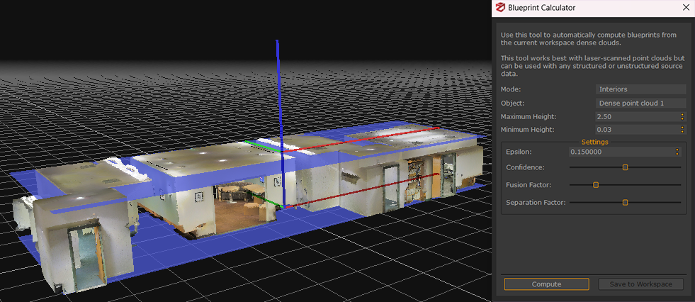
Once the user has selected the appropriate mode (interiors vs exteriors) and confirmed the automatically detected floor and ceiling planes, 3DF Zephyr will automatically compute and save the blueprints (polylines and surfaces).