Orthophoto generation
These functions are not available in 3DF Zephyr Lite and 3DF Zephyr Free.
3DF Zephyr is used in various geographic measurements, including orthophoto generation that results from the application of drones to support topographic and land surveying activities. The generated orthophoto use the camera information to ensure that the dimensions represented are correct, without concerns about image distortions.
Starting the Orthophoto Creator Wizard
From the “Workflow” Menu , you can find three different orthophoto generation options :
- Orthophoto from sparse points (requires to have generated sparse points cloud).
- Orthophoto from dense points (requires to have generated dense points cloud).
- True Orthophoto from Mesh (requires to have generated the mesh).
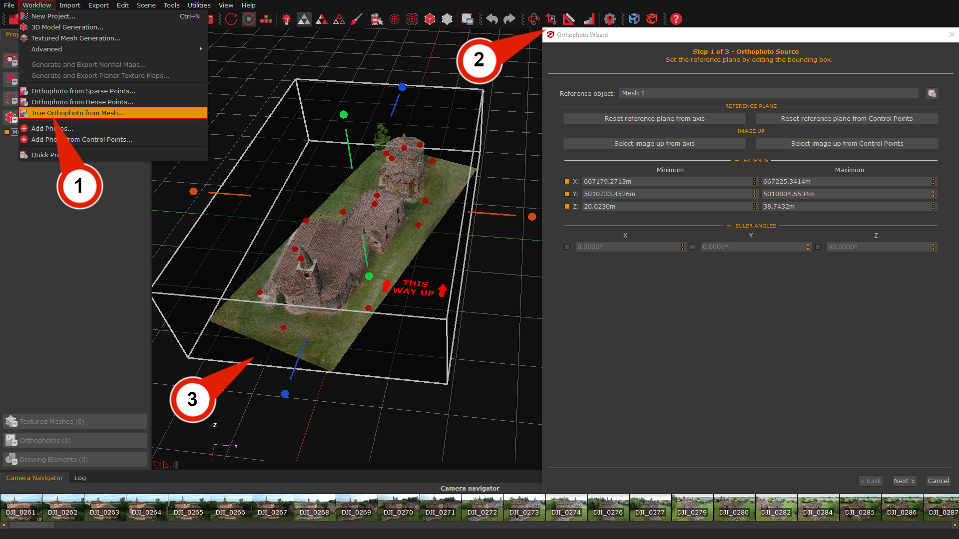
When you select "True Orthophoto from Mesh" (1) option, the Orthophoto Wizard (2) window will open, and a Bounding box (3) will also appear in the 3D workspace.
Step 1 - Orthophoto source
The first orthophoto wizard page will allow to define orthophoto's limits by changing the dimensions of the bounding box in the workspace, and it will be possible to set the reference plane from another axis or at least 3 GCPs. The first step is to choose the Reference object (4) among the created meshes; the Adapt Bounding box (5) button allows to change the mesh's bounding box size automatically.
The Orthophoto wizard's default settings will create an orthophoto of the entire 3D object with the reference plane on the Z axis. The functions below will allow to set the reference plane from another axis or use GCPs as a reference. While changing the reference plane or the image up direction, it will be possible to see a preview on the bounding box represented by the red text: 🠝THIS WAY UP🠝 (6).
Note: for practical reasons, it is best to change the Reference Plane and Image Up directions first, as this will reset the bounding box size each time.
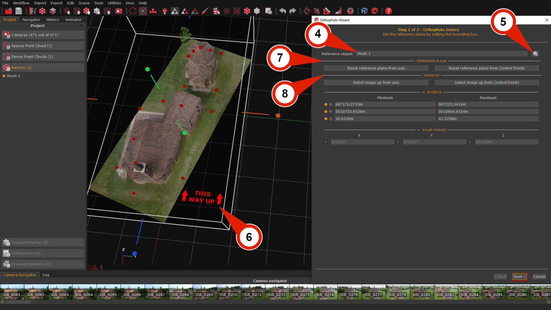
Reference Plane section (7)
- Reset reference plane from axis: this function allows to set the normal of the orthophoto's reference plane from a chosen axis.
- Reset reference plane from Control points: this function use at least three control points to define a plane on which you want to generate the orthophoto. The plane normal will be the new world up vector, and yellow line will be visible in the workspace as a preview during the GCP's placement.
Image Up section (8)
- Select image up from axis: This function uses the chosen axis to orient the image up direction of the orthophoto.
- Select image up from Control points: This function uses two chosen GCPs to orient the image up directions of the orthophoto.
Extents section
These commands allow you to resize the Bounding box on the XYZ axes. Through the check-boxes, it is possible to restrict one or more axes on which to resize the Bounding Box.
Euler Angles section
These commands allow you to rotate the Boundingbox on the XYZ axes. Through the check-boxes, it is possible to restrict one or more axes on which to rotate the Bounding Box.
Once the source of the Orthophoto has been set, you can proceed with the "Next" button.
Step 2 - Resolution
This page of the orthophoto wizard will present a set of options to define the orthophoto resolution by changing the Ground sample distance and other parameters, or can also set the resolution by specifying the image size.
A preview will be shown in the rendering window, while the green rubber band (9) will define boundaries within the orthophoto image.
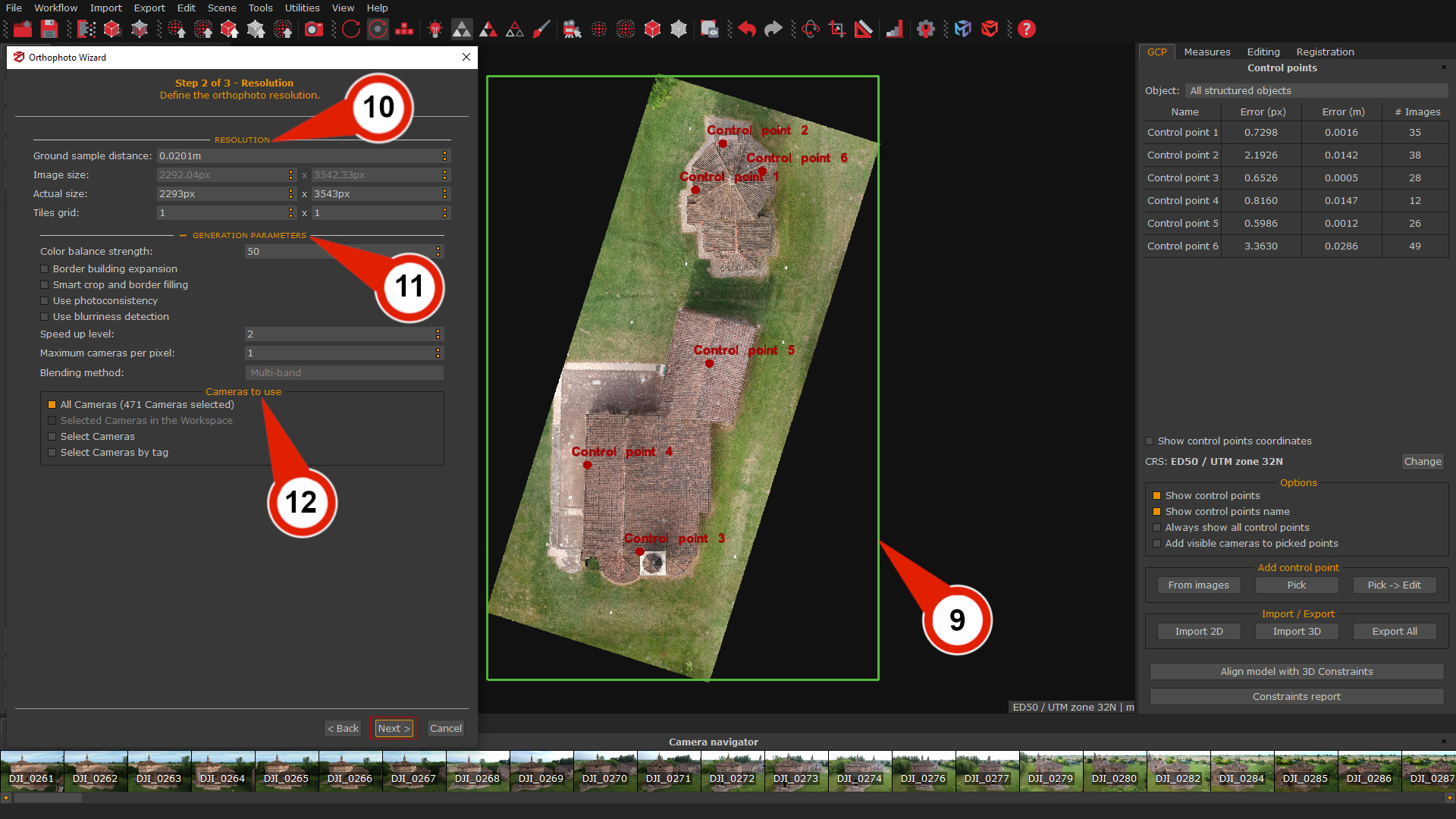
The orthophoto wizard Resolution page is organized settings are organized into 3 sections:
- Resolution (10): This section defines GSD and the actual size of the orthophoto. The orthophoto Width and Height are possible to adjust according to the desired Ground Sample Distance, or you can set the GSD directly and let 3DF Zephyr calculate the parameter(s) for you. The Tiles Grid parameters allow setting the Tiles per height and Tiles per width to define the numbers of vertical and horizontal tiles used to split the orthophoto. Setting these parameters could be fundamental for huge orthophoto or computers with a low amount of memory).
- Generation parameters (11): allows controlling every pixel's color generation mode. This system is very similar to the texture generation system. We advise leaving the color balance with 1 camera per pixel; however, if you wish, you may use more cameras for a different color weight. If this happens, you may choose between an algorithm blending method:
Multiband: will use the mean to compute low frequencies and the best images to compute the high frequencies. This is usually a better choice than Mean because although it is less prone to lighting changes (usually just a little worse than mean), the resulting image will be more in focus and sharp by preserving high frequencies.
Mean: will weight the color source depending on the view angle and the distance. Although it's robust to lighting changes, the mean won't keep high frequencies, so will be less in focus and sharp.
- Camera to use (12): allow the choice to ignore cameras during the generation process by cameras directly or by tags.
Step 3 - Exporting settings
This section allow to choose the export settings and the appearance of the orthophoto.
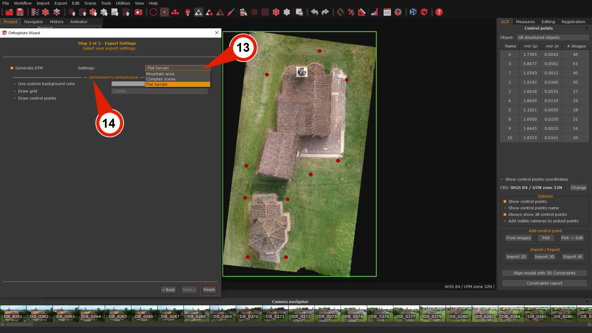
- Generate DTM (13): selecting this flag will automatically generate a DTM (Digital Terrain Model) file according to the scene type. It's possible to choose three different scenarios (Mountain area, Complex scene, and Flat terrain).
- Orthophoto appearance (14): this section enables/disables the drawing for customizing the control points and grid on the orthophoto if desired.
When everything is ready, click "Finish".
Note: Zephyr will automatically open its DEM viewer utility when the process has finished.
Save the orthophoto outside Zephyr
At the end of the generation process the new orthophoto will be listed in the Project tab under section Orthophoto.
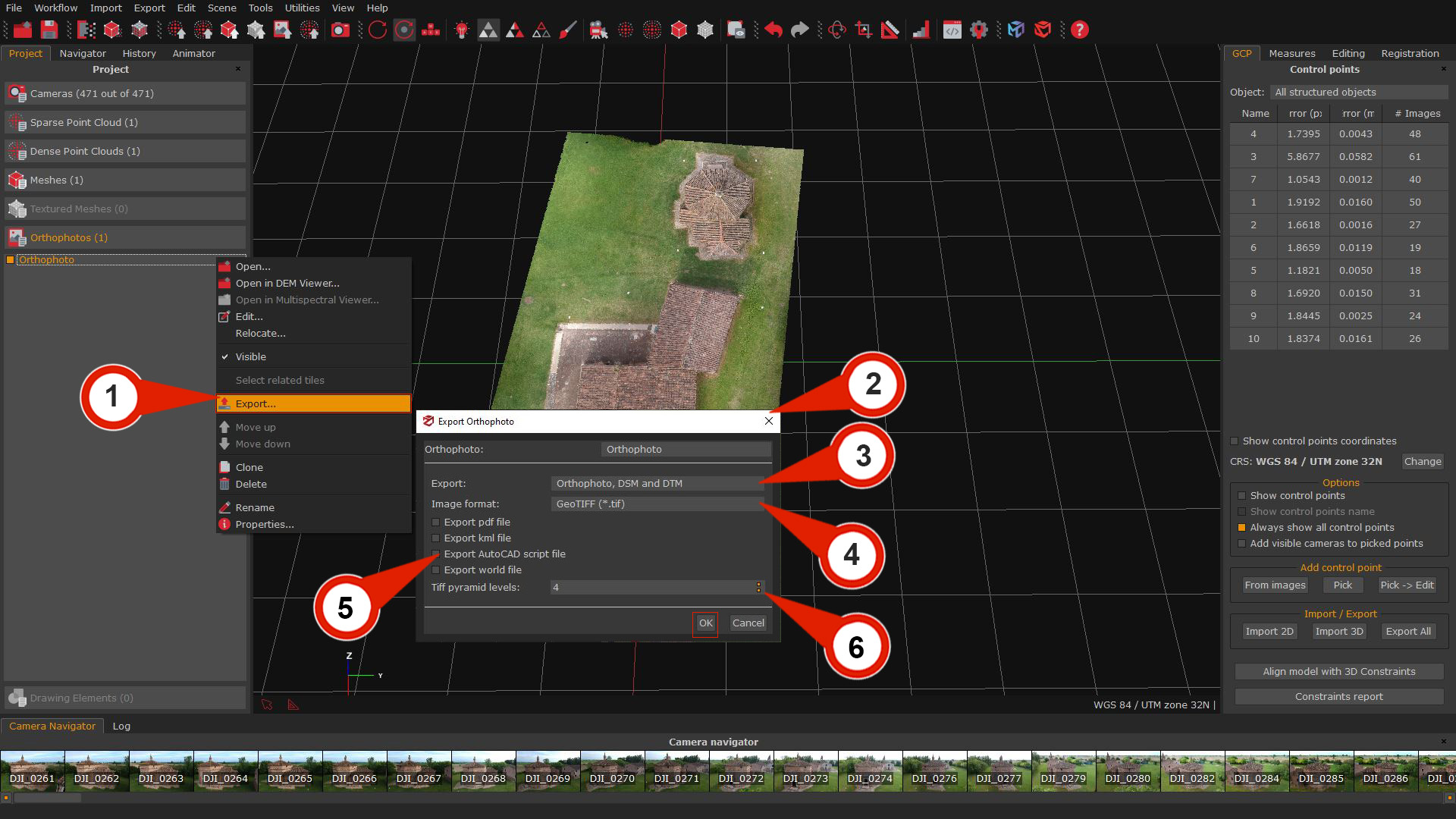
By right-clicking on the orthophoto will be possible to chose the option "Export" (1), and the Export orthophoto (2) window will appear.
- Export (3): the drop-down menu offers the option to export only the orthophoto, the DSM, DTM or all the files.
- Image format (4): this drop-down menu allows you to save the orthophoto in these image formats: jpg, png, and tiff.
- Export Pdf file: exports the orthophoto in Pdf format.
- Export KML file: by enabling this checkbox, you can export an orthophoto in KML format for Google Earth.
- The Export Autocad Script File (6) flag allows the export of a .scr file that will automatically load the orthophoto within Autocad, with the correct scale settings set in 3DF Zephyr.
- Export World file: exports the World file.
- The Tiff pyramids level (5) parameter will allow storing inside the generated tiff orthophoto a pyramids levels layers, which can improve the display of raster data by retrieving only data at a specific resolution required for display.
After establishing the parameters for saving the orthophoto, click "OK".A preview (6) of the exported files will be shown in the Save As window, Select the file name and destination folder, and then the "OK" button to save.