3D facial capture using a custom-built photogrammetry setup for Orthodontics
Digital Orthodontics, Facial Capturing, Medical Engineering
The data for this case study has been kindly provided by Hans Wellens – a Belgian orthodontist who obtained a Ph.D. at Radboud University Nijmegen in the Netherlands. The project has been carried out in collaboration with Hanne Hoskens, Peter Claes, Anne Marie Kuijpers-Jagtman, and Alejandra Ortega-Castrillón from different universities in Belgium and the Netherlands.
The article was recently published in the American Journal of Orthodontics and Dentofacial Orthopedics (Volume 158, Issue 2, August 2020).
![]()
You can download the full paper by clicking the following link.
Project goals
The project aimed to develop a custom-built photogrammetry system for 3D facial capture, to be used for orthodontic diagnosis and treatment planning. The rig had to come in a cheaper, while still performing competitively compared to other hardware solutions already available on the market.
The researchers compared their custom “Stereo-Face 3D” or “SF3D” system, to a state-of-the-art system from 3dMD, the 3dMDFace. In particular, they tested both systems with a group of 30 subjects and a mannequin head to evaluate and compare their accuracy and reliability.
Systems used
The custom-built SF3D system presented in the project was developed by Hans himself and consisted of 14 Canon EOS 1200D reflex cameras equipped with Canon 18-55 mm EF-S lenses (Fig. 1). The cameras were mounted on a square aluminum frame in a hemispherical way, to better capture the whole human face. The frame was attached to a wheel mounted support assembly, which provided a working surface for the control switches and laptop, and housed the power supplies.
Aside from the cameras, the frame also supported 3 remote-controlled LED panels, to avoid shadows. Patient positioning was facilitated by 2 diode line-lasers on either side of a mirror in the center of the frame, whilst random pattern laser dots provided additional texture, essential to a successful reconstruction.
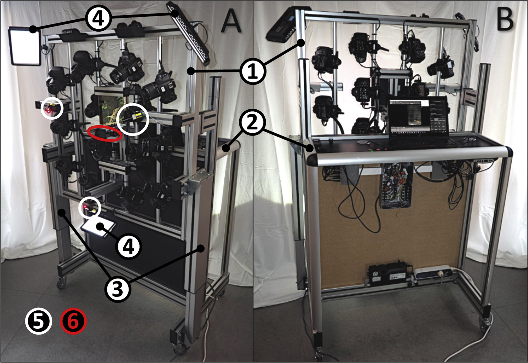
Camera settings and image shooting were controlled using a Smart Shooter 3 GRID software, whereas the imported images were processed using 3DF Zephyr Pro 4.002 (now discontinued).
Four 3DF Zephyr coded targets placed on a headband enabled correct scaling of the model. The headband was placed as high as possible on the forehead while ensuring that the coded targets were visible from enough cameras as well.
The other solution commercially available system tested for comparison was 3dMDFace, a hybrid structured light stereophotogrammetry system made up of 3 (stereo) pairs of 2 cameras each: one pair is positioned centrally in front of the patient, and the other two are placed on either side.
Data acquisition
The next step was testing both solutions by scanning a study group of 30 volunteers belonging to diverse ethnicities, recruited from the University Hospital Gasthuisberg in Leuven, Belgium. Participants had to meet multiple inclusion criteria which, together with the age and sex distributions of the sample, can be found in the complete paper (Wellens et al., p. 291). To account for the highly variable nature of human facial expression, researchers repeated the image acquisitions three times in a row for each individual.
Compared to the study group, a mannequin head was scanned three times consecutively with each system, to evaluate the two solutions in a scenario without any biologic variability (Fig. 2-3).
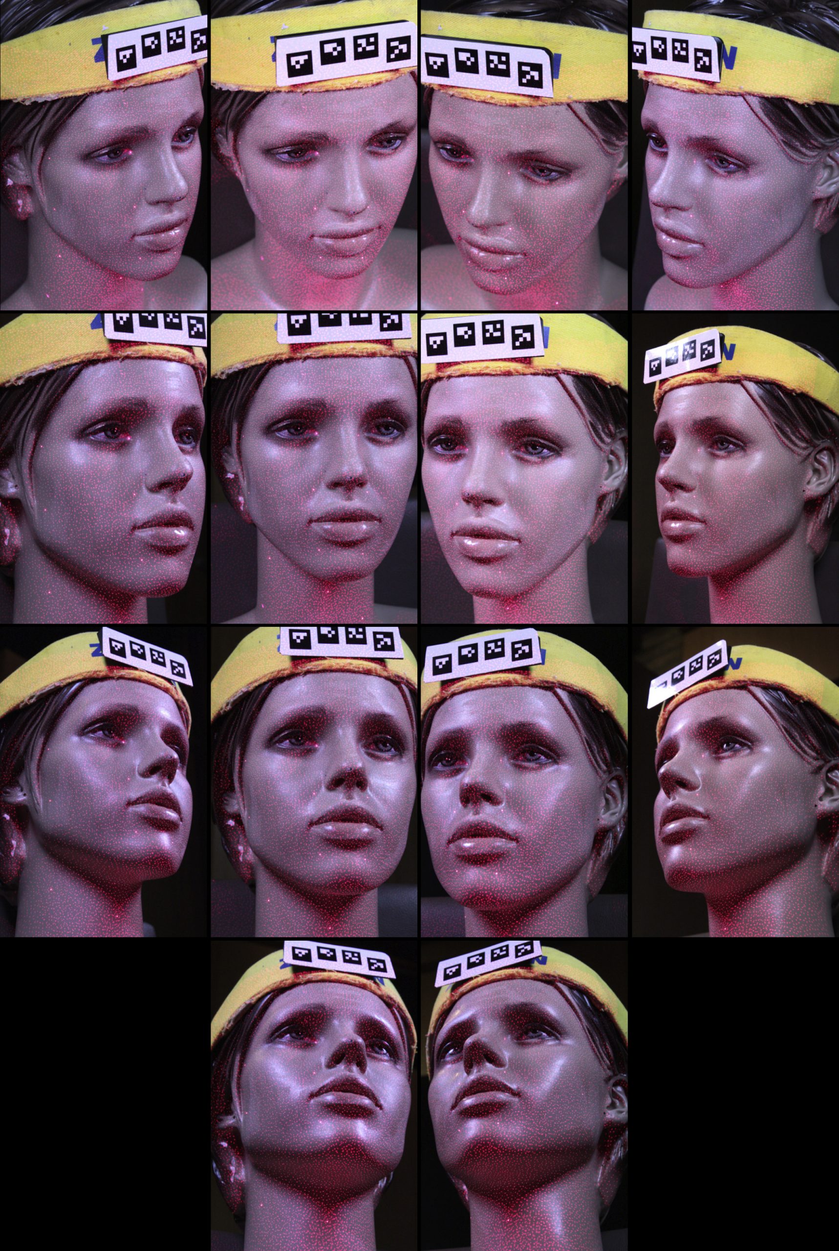


Fig. 3. Screenshot of the 3D model of the mannequin head colored mesh (left) and mesh geometry (right) generated with 3DF Zephyr.
Afterward, all the acquisitions were analyzed using MeshMonk, an open-source software toolbox allowing for mapping an anthropometric mask onto a given 3D facial surface.
Final results
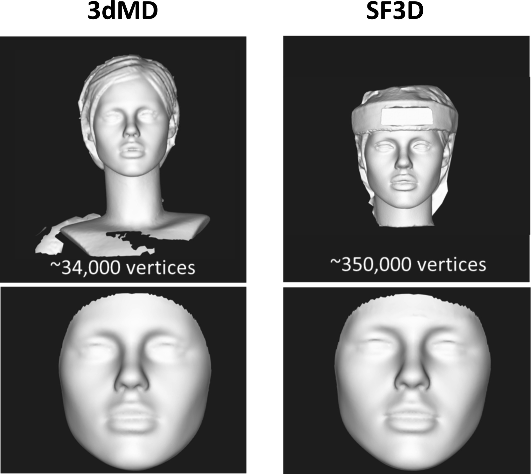
On average, facial meshes from the SF3D system had about 350,000 vertices, while those extracted from the 3dMDFace system had approximately 34,000 (Fig. 4). However, the headband mounted 3DF Zephyr markers used in the custom-built system forced a reduction in the forehead area included in the analysis, in order to compare all the meshes generated by both solutions.
According to the paper, systems validation showed that “The variability values of the custom-built setup presented here were competitive to a state-of-the-art commercial system at a more affordable level of investment.”
More specifically, the intrasystem shape variability expressed as RMSE (root-mean-square error) for 3dMDFace and SF3D was 0.52 ± 0.07 mm and 0.44 ± 0.16 mm, respectively, and the corresponding values for the mannequin head were 0.42 ± 0.02 mm and 0.29 ± 0.03 mm, respectively. The intersystem shape variability RMSEs was 1.6 ± 0.34 mm for the study group and 1.38 mm for the mannequin head.
Please refer to table II of the paper (Wellens et al, p. 296) for the complete list of values.
To sum up, final results stated that the custom-built SF3D was slightly more precise and more variable than 3dMDFace, and its overall performance matched and, at times, surpassed that of 3dMDFace.
Further information, including an explanatory video, can be found in the author’s Researchgate project log at this link.