Photogrammetry for hull design and boat modeling
Marine Engineering, CAD Drawing, Reverse Engineering
All data shown below have been kindly provided by Marine Engineer Edgar Tovar of A.T. Suministros S.A. de C.V., a marine engineering and naval architecture firm based in Cancun, Q. Roo, Mexico.
![]()
The following case study features a photogrammetry approach to hull and boat 3D reconstruction using 3DF Zephyr Lite, Rhinoceros 7, and Orca3D.
Project’s goals and photo acquisition
Naval architecture may turn out to be a real challenge for image-based scanning since several complications – mostly uniform and reflective surfaces – must be considered.
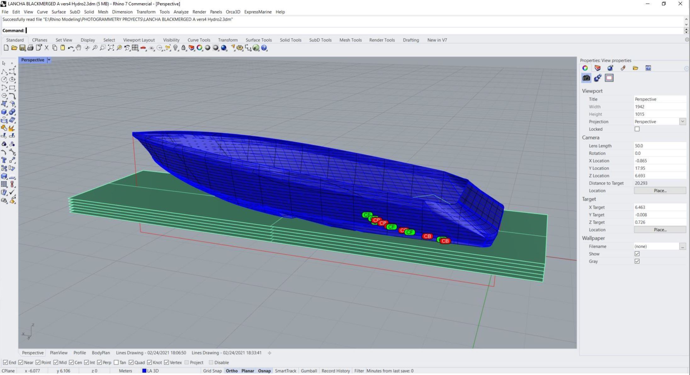
Modeling the hull’s shape in a CAD environment – thus supporting hydrostatics and stability analysis – was the firm’s final goal, while the 3D reconstruction in 3DF Zephyr was leveraged as a reference for NURBS modeling in Rhinoceros and Orca3D.
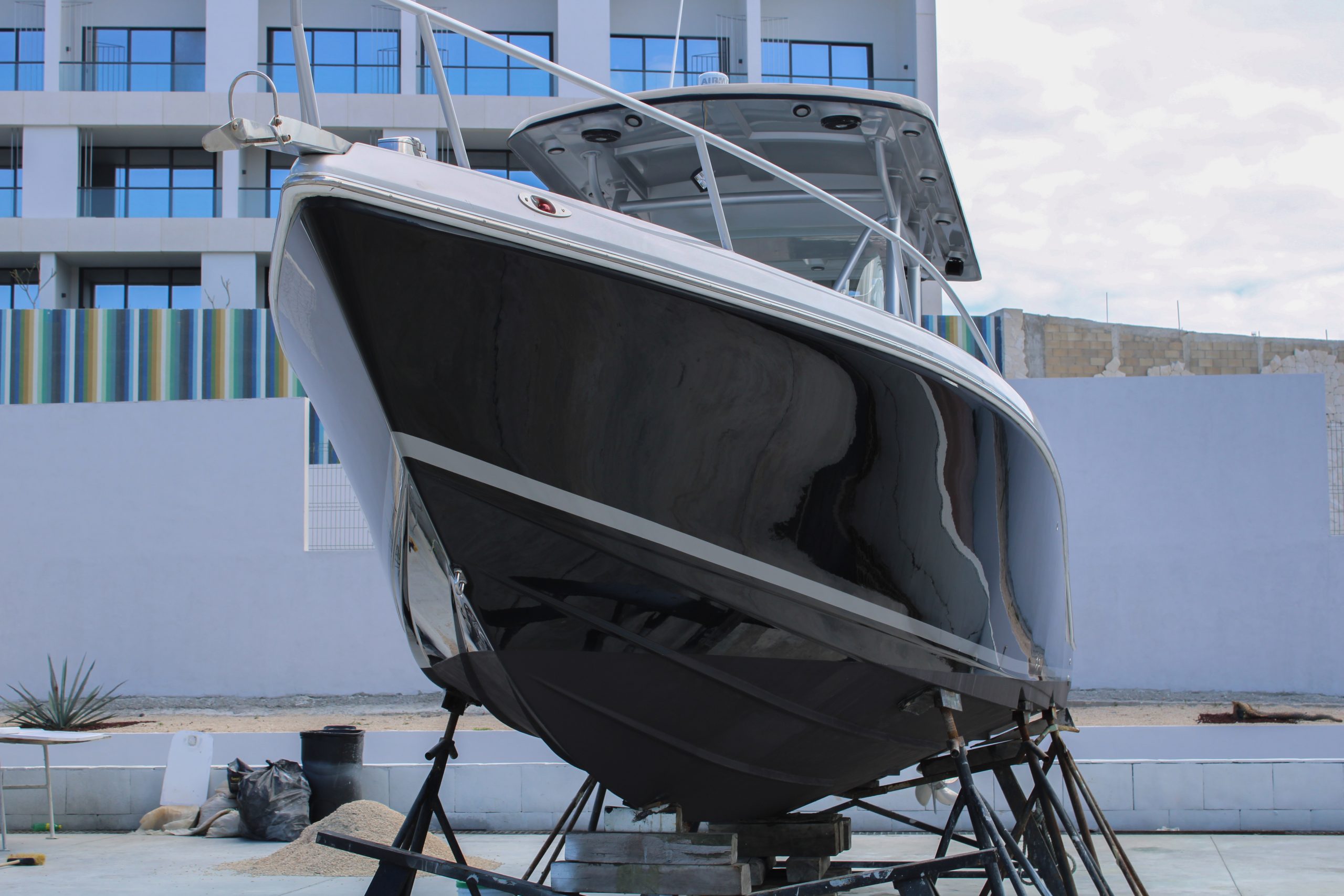
The firm engineers first focused on scanning a small yacht to give photogrammetry a try and figure out further applications to larger commercial vessels. Indeed, a hand-held camera and a ladder were enough for the photo acquisition during that preliminary test. The camera model was a DSRL Canon EOS Rebel T7 with a CMOS sensor of 24 MP equipped with a Zoom Lens EF-S 18-55mm.
263 pictures in JPG format were taken from an average distance of 4.5-5 meters and at three different heights between 0.7 and 1 meter, while the picture baseline was about 1.2 meters. Besides, the boat’s waterline drawn in white paint between the dark painted sides and the bottom was a helpful physical reference during the shooting phase.
Of this dataset, a round of 72 close-ups was taken from the bottom to the keel of the boat setting a shorter distance (1.8 to 2.3 meters). The referred bottom photographs were taken due to the so-called “planning hull” with a stepped chine and several bottom cross-section breaks that had to be properly reconstructed (Fig. 1).
Data processing and CAD vectorization
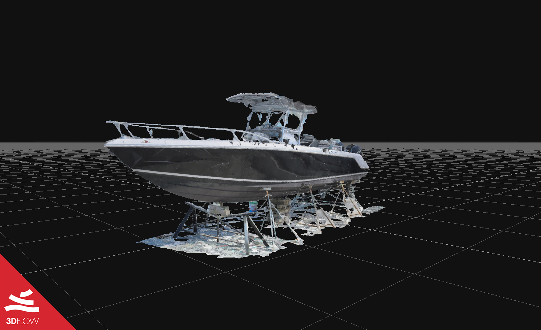
Despite the extremely shining, almost glossy surface and the light conditions (direct sunlight) during the shooting, 3DF Zephyr managed to orient 238 out of the 240 final pictures and 3D reconstruct the whole boat surface (Fig. 2). The final mesh came with geometry and texture artifacts. However, since the 3D model itself was not the primary goal for this specific scenario but rather a “raw” piece of data to use as input for the next vectorization step, there was no need for a further photo acquisition with better light conditions to achieve an overall better quality.
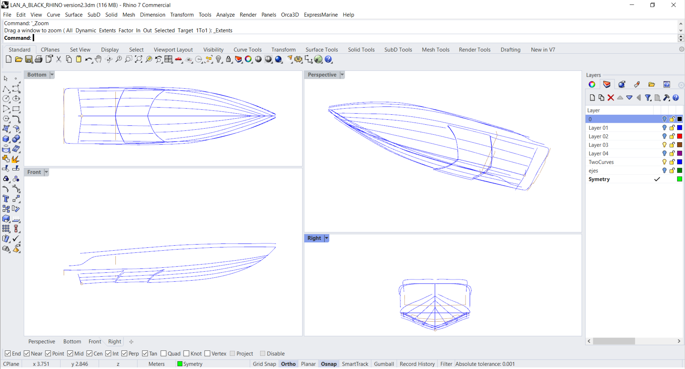
The 3D model generated with 3DF Zephyr was exported in .obj and later converted in .dwg file format using the “reaConverter” standard software app. The latter file was finally imported into Rhinoceros 7, centered and projected in its X, Y, Z cartesian axes in “Arctic view” mode for proper visualization and a higher resolution of its curves in order to vectorize the lines of the hull (Fig. 3).
This step can also be accomplished with the full version of 3DF Zephyr as it allows for importing, creating, and edit drawing elements which can be exported in the following file formats: .xml, .shp, .dxf, and .dgn.
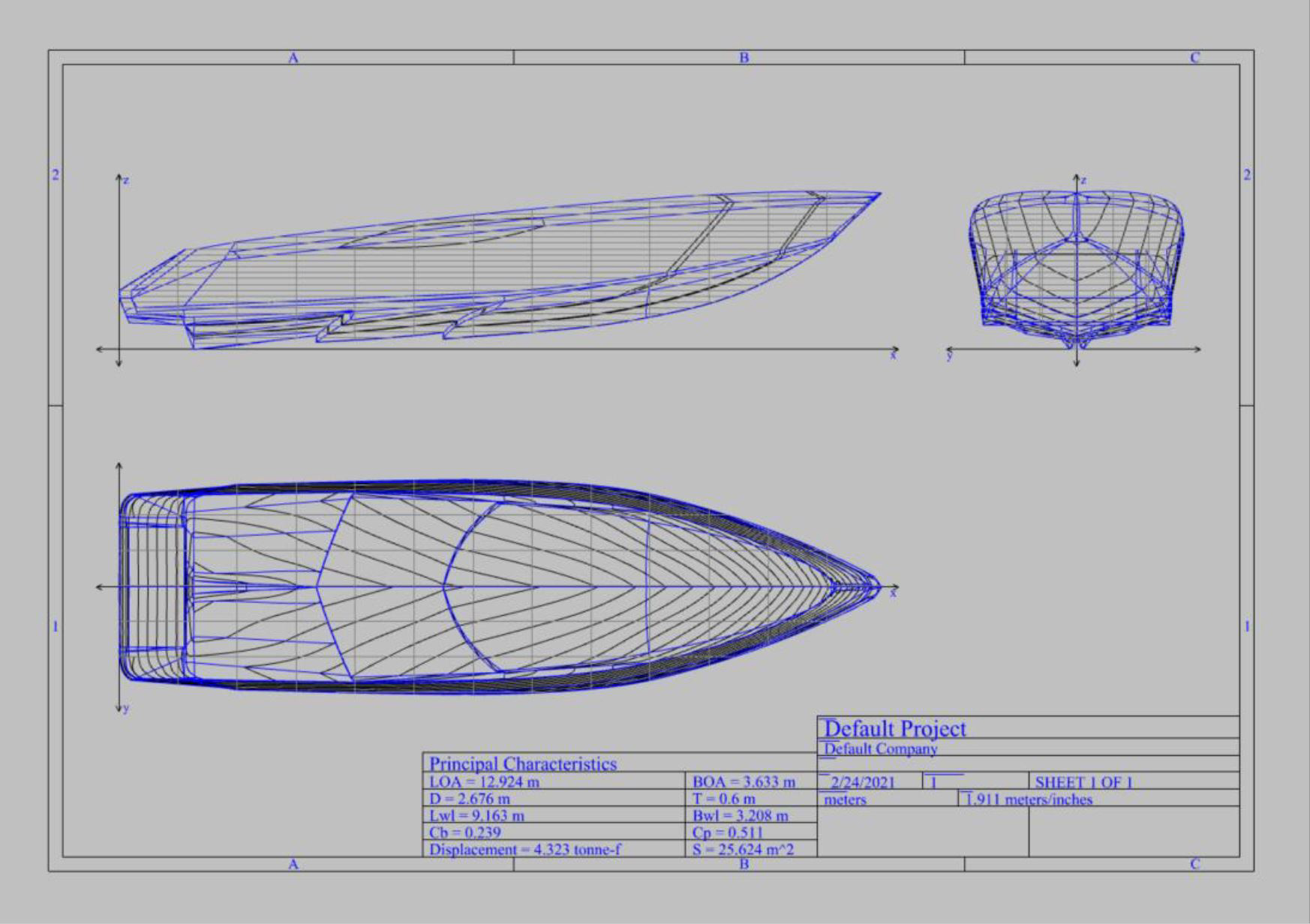
Size details of the boat such as length, breadth and depth were known, meaning that the 3D scale factor could be adjusted with CAD software scaling tools once the file was imported and the vectorization process fulfilled. (Fig. 4-5).
Reverse Engineering process
Orca3D, which runs on top of Rhinoceros 7, was leveraged to generate the desired naval architecture calculations.
The described reverse engineering process has multiple derived applications, including:
- Recovering the lines of form of an existing vessel;
- CAD drawings generation for structural modifications; refurbishment of the boat; building a sister boat;
- Naval architecture calculations, Power and CFD modeling and predictions;
- Hull’s external surface measurements and list of materials when repairing, cleaning and painting the vessel;
- Insurance, Class Inspection records, boat owner’s maintenance records.