We want to start the new year with some fresh news from the 3Dflow Development team; so, without further ado, let’s see the most interesting features that will be introduced in the next update of 3DF Zephyr!

Mesh enhancements
In view of the forthcoming update, the photoconsistency algorithm of 3DF Zephyr has been furtherly optimized to allow better management of high frequencies during the similarity check between pair of images. Visually speaking, this is displayed in a more accurate mesh output and, in particular, in highlighting more details on the 3D model surface, as shown in the slider below:


Old Photoconsistency optimization (left) vs New Photoconsistency optimization (right).
Volume of Interest (VoI)
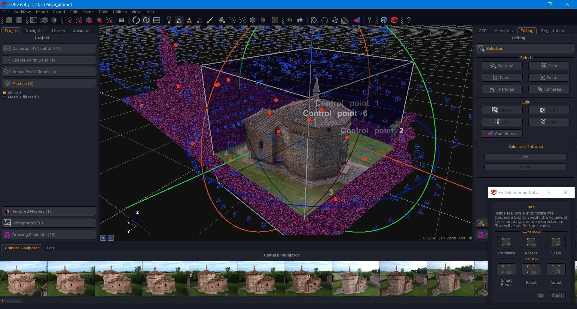
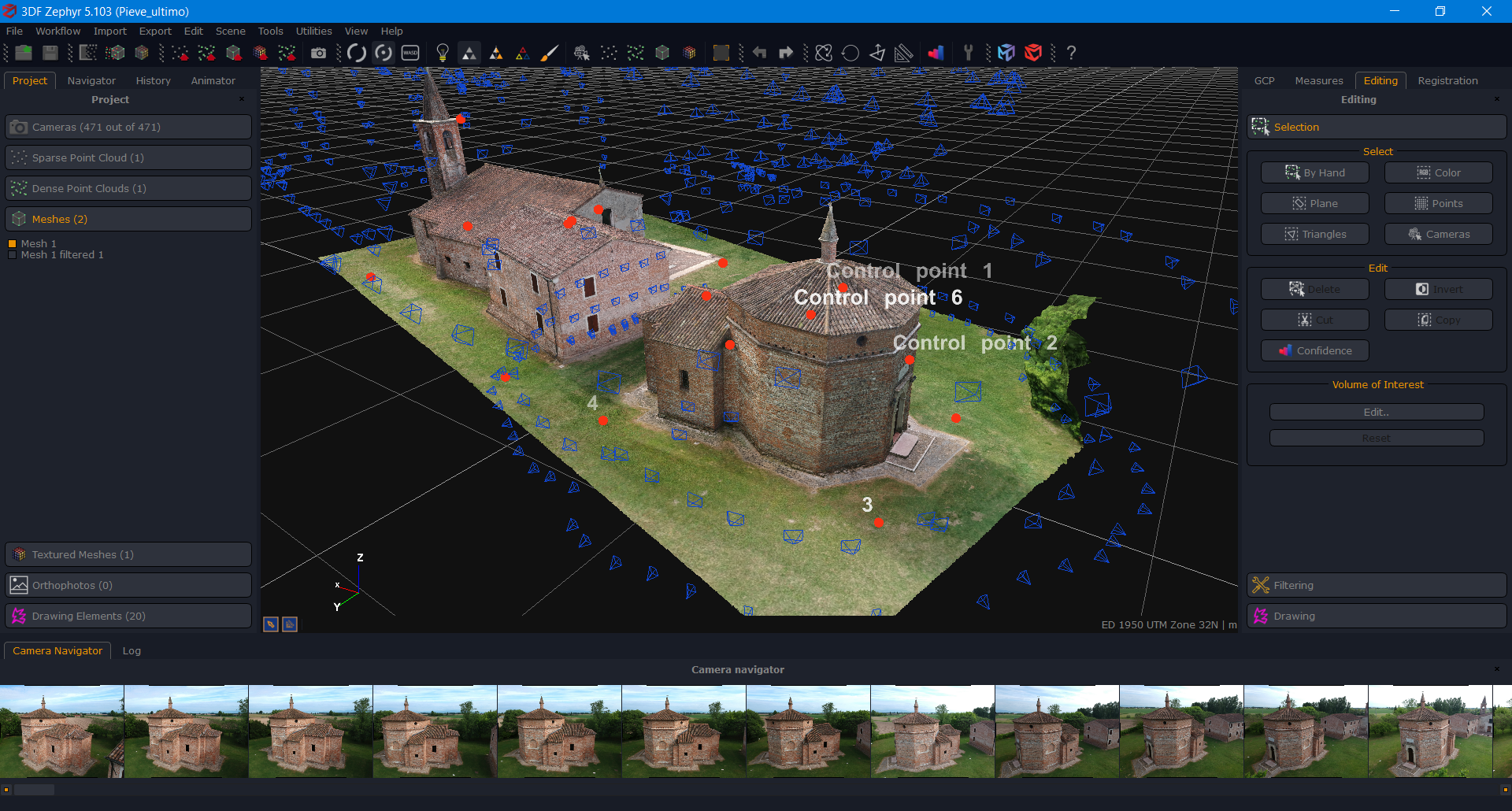
The Volume of Interest (VoI) is a new experimental feature designed to aid users during the visualization and editing of huge datasets. The user specifies a three-dimensional clipping region by visually editing it (works very similar to the bounding box editing tool).
Objects (Dense Point Clouds, Meshes, and Textured Meshes only) outside this region are clipped and will not be displayed (but the underlying data will still be there), thus reducing the display resource usage, especially in taxing datasets. Besides, filters used while the VoI is set will only be applied to the visible part, thus speeding up the process.

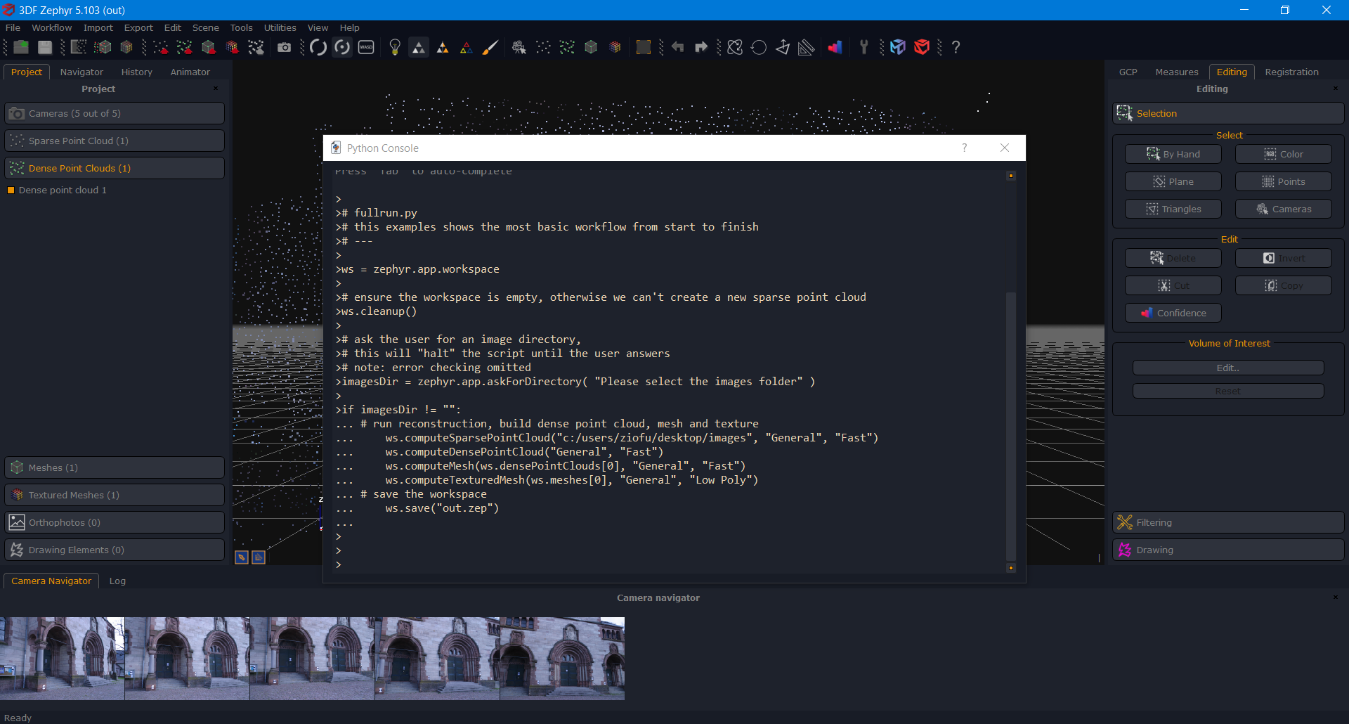
The new Python console enables a brand-new way to interact with the 3DF Zephyr workspace and its objects. It’s not meant to supersede the batching tool but allow more experienced users to automate and simplify specific workflows.
Examples of exposed functionality are running an entire reconstruction from images to textured mesh and applying a filter to a specific mesh.
This tool is still being tested, and we are waiting for feedback from our user community to improve it further. However, tips and guidelines will be available soon.
3DF Zephyr already allows for automatic coded target detection; however, our latest implementation now improves the manual marker detection algorithm to find the cross pattern at their center more accurately. Just draw a rectangle over said pattern, and Zephyr will pinpoint its center, adjusting the control point accordingly.
Coded targets are meant to speed up post-processing activity and, specifically, drive the control point placement accuracy. They mainly affect the mining, construction, and architecture industries but can also be leveraged in mapping and surveying and the Cultural Heritage field.
Sphere Detection
We are also launching a sphere detection tool along with the marker detection update. How does it work? In the picture, simply draw a rectangle over the sphere you want to be found, and Zephyr will place the control point at its center.
Sphere detection aims to play a game changer role in the forensics industry, i.e., for supporting the analysis of the line of fire in crime scenes where the spheres on the trajectory rod are scanned by a laser scanner.
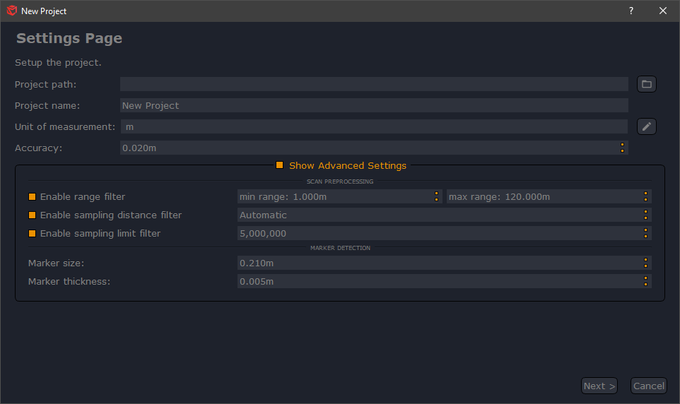
From the next update, 3DF Scarlet’s user experience will significantly change thanks to a “non-blocking” rendering that will ensure a better and more fluid scan visualization within the software. In addition, users will be able to automatically perform some basic preprocessing on a project’s scans such as:
- range filtering – culling all the scan points outside the given range;
- sampling distance filtering – reducing the number of points closer to the scans’ origin, where you expect to have a higher point density;
- sampling limit filtering – making sure that each scan doesn’t exceed a defined number of points.