Photogrammetry + LiDAR with the DJI Zenmuse L1
Aerial Photogrammetry, LiDAR module, Mapping, Drone Survey
The data of the following case study were kindly provided by Simone Dall’Asta of DL Droni, an Italian company specialized in delivering aerial surveys for different applications, such as the inspection of infrastructures and photovoltaic parks, precision agriculture and environmental analysis.

Simone has recently carried out surveys with the drone DJI Matrice 300 RTK, equipped with Zenmuse L1 technology, DJI’s first solution that integrates together RGB data and LiDAR module to reach optimal point cloud and 3D mesh accuracy, with the photorealistic detail derived from photogrammetry.
This article will show the different workflow steps to follow in 3DF Zephyr.
Survey overview
The survey shown below was performed last November 2021 during a cloudy day over a small town located in the province of Cremona, Lombardy, Italy. The dataset, mainly being a test to understand the functionalities of the LiDAR L1 module, includes only 211 nadiral photos in JPG format with 50% overlap, plus a laser scan in .las format. The Matrice 300 RTK was connected to the HxGN SmartNet’s GNSS network to ensure better real-time monitoring of the drone’s position; the flight mission was planned at a 60 meters height with the “triple repetitive echo” setting activated, for a total flight time of 11 minutes (with automatic L1 IMU calibration at the beginning and end of the mission).
The parameters selected for the photo acquisition are the following:
- Shutter speed: 1/30 seconds
- Aperture: f/2.8
- ISO: between 160 and 320
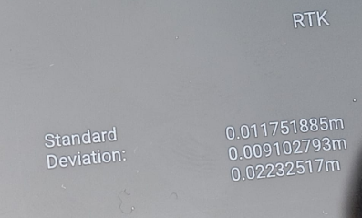
Here below you can see the RTK flight deviation (Fig. 1):
Workflow in 3DF Zephyr
After the data collection, the first step was to generate the 3D model from the photogrammetric data in a 3DF Zephyr session. Once the photogrammetric project was completed and saved, the .las file of the LiDAR was imported in another Zephyr session to use as a reference model for photogrammetric data + laser scanner integration.
This step was straightforward: the photogrammetry .zep project was imported and merged with the project containing the .las file via the “Direct merge” option present in the dialog that automatically pops up during the import phase.
As you can see from the screenshot below (Fig. 2), the two types of data are in the same reference system; thus, you can proceed directly to the structuring phase of the laser scan point cloud by right-clicking on it in the Project tab.
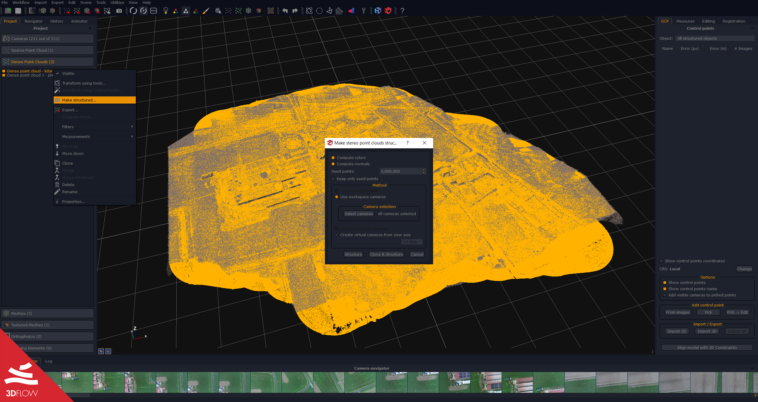
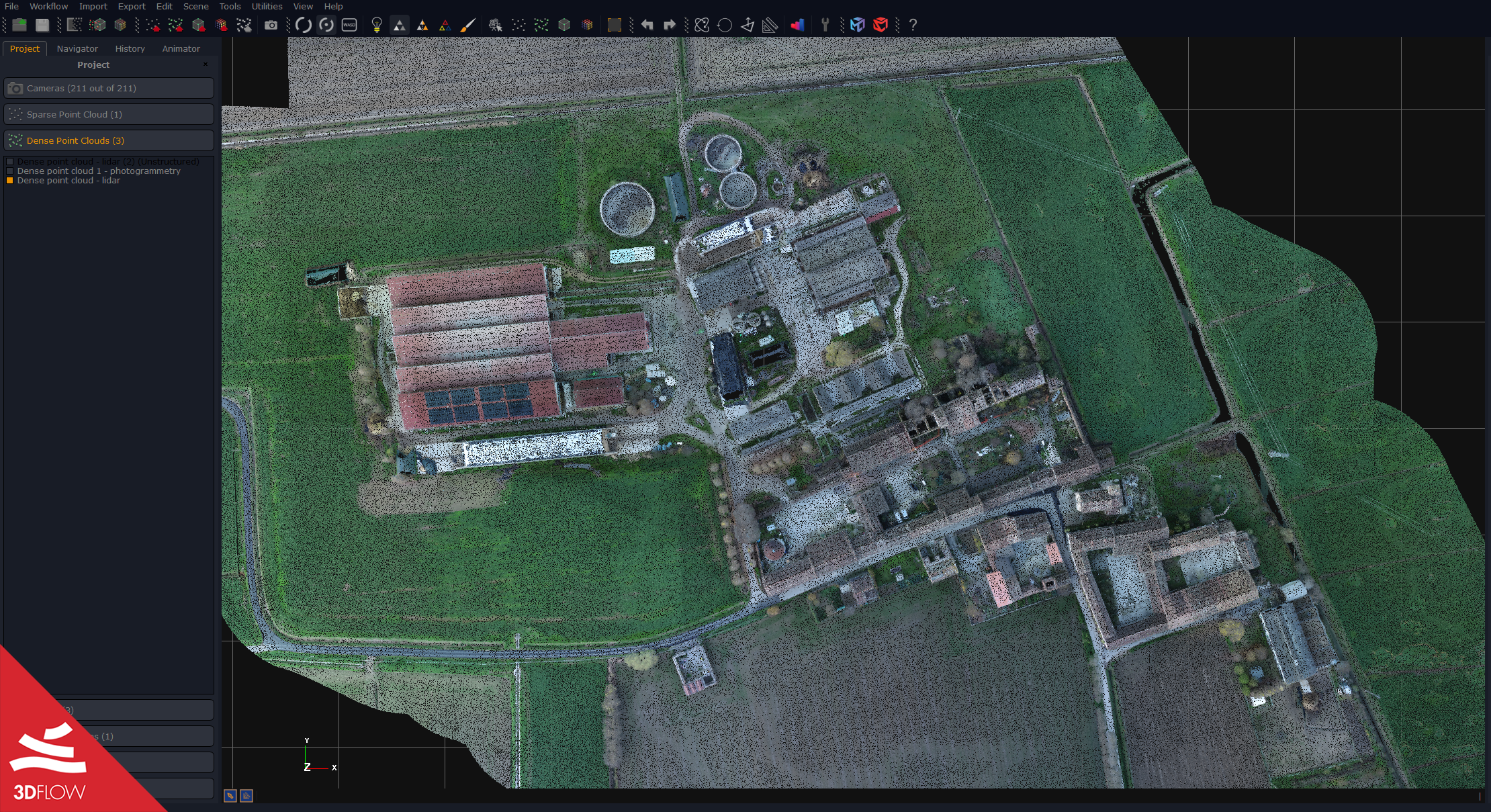
IMPORTANT: to colorize the laser scan with the RGB data from pictures, you must structure it using the workspace cameras as shown above. This fundamental step leads the laser scan to behave like a standard photogrammetric point cloud (Fig. 3), allowing you to go ahead with the subsequent phases of the 3D reconstruction, i.e., the stereo mesh textured mesh generation.
Outputs and final thoughts
The final phase of the textured mesh generation – using the “Generic – High Details” presets – extracted a mesh with 10,559,890 triangles and 6,534,960 points.
Considering the small number of pictures taken for the area to reconstruct, the result, especially in terms of geometric accuracy, totally met the expectations. For this kind of aerial survey with an urban scenario, increasing the number of photos (and, therefore, the overlap between them) while managing to take both nadiral and oblique shots would then increase the photorealism level as well, specifically when it comes to buildings sidewalls.
Below are screenshots of the final mesh – geometry and texture, respectively (Fig. 4).


Fig. 4. Final mesh, geometry (left) and texture (right). ©DL Droni