Tutorial #A08 : Contour lines, sections and track sections generation
Sections and contour lines
Welcome to the 3DF Zephyr tutorial series.
You will learn to automatically create sections, contour lines, and track sections directly with 3DF Zephyr.
This tutorial cannot be completed with 3DF Zephyr Free or Lite versions.
Introduction
Given a dense point cloud or mesh, 3DF Zephyr allows you to create sections, contour lines, and track sections that can be exported to CAD and GIS file formats.
Click on “Tools” (1) > “Sections and contour lines”(2),
You can select:
- Sections (3): this tool allows for creating sections once you have selected the target object (dense point cloud, mesh, or textured mesh). The size, position, and orientation of sections are fully customizable by leveraging the settings panel. Using previously placed GCP or the reference system axes to orient the section plane is also possible.
- Track Sections (4): this tool requires at least two control points. A certain number of sections will be generated between a control point and the next. The size, position, and orientation of sections are fully customizable by leveraging the settings panel.
- Contour lines (5): this tool allows for creating contour lines once you have selected the target object (dense point cloud, mesh, or textured mesh). The size, position, and orientation of contour lines are fully customizable by leveraging the settings panel.
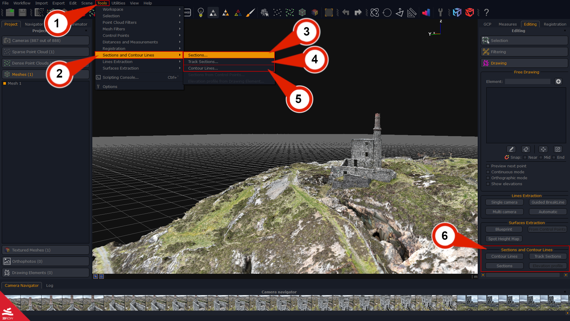
You can also select sections, track sections, and contour lines tools by clicking the Editing tab and opening the Drawing elements (6) section. They can be exported as drawing elements to the following file formats: .xml, .dgn, .dxf, .shp.
Note: the sections and contour lines tools described below refer to the mesh as the target object. Please see the “Sections and contour lines generation from Dense Point Cloud” part if you plan to use the dense cloud as the target object to create sections and contour lines.
Sections generation
Click the “Sections” (1) button from the Editing tab > Drawing elements. Alternatively, click on Tools > Sections and Contour lines > Sections to start.
The Section settings window (2) will pop up while a blue plane (3) will overlap the 3D model in the workspace.
Select the Target object (4) and adjust the blue plane size, position, and rotation using either the gizmo (5) or the Section settings window (2).
The sections window also allows to:
– place the plane(s) using the GCPs if they have been previously added;
– place the plane(s) using one of the reference system axes;
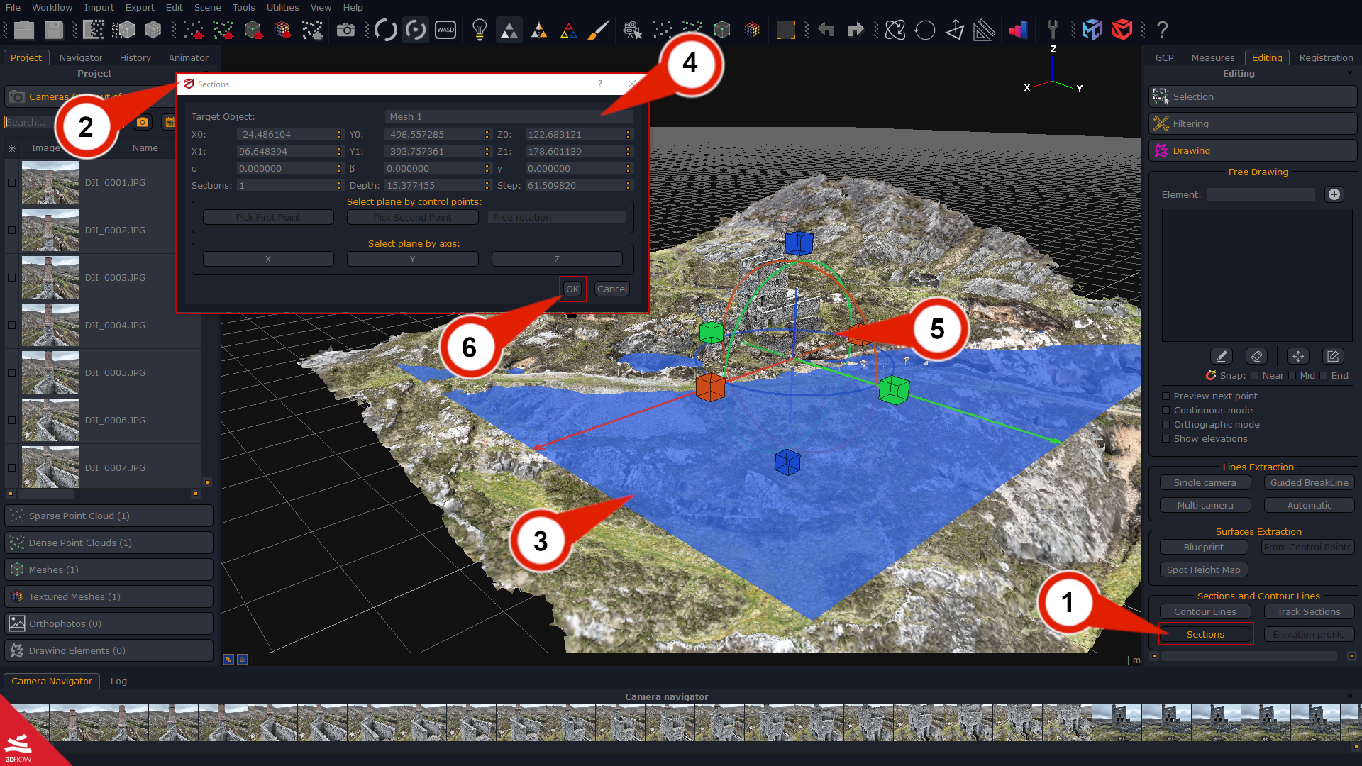
You can also define the plane’s depth and step (these thresholds get metric units when the 3D model has been scaled). Please, consider the number of sections will change as the step value varies and vice versa.
Once done, click the “OK” (6) button and the new sections will be listed in the “Project” tab as drawing elements.
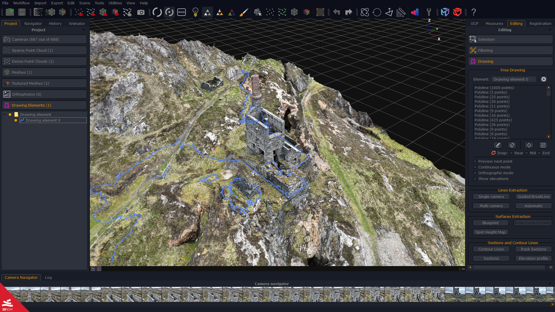
Here below the Single section generation applied to a mesh:
Track sections generation
You need to place at least two control points on the 3D model before using the Track sections tool, and please notice that GCPs in the area of the 3D model you want to create track sections on.
Click the “Track sections (1)” button from the Editing tab > Drawing elements, or click Tools > Sections and Contour lines > Track sections to start.
The Track section settings window (2) will pop up while a group of pink planes (3) – identifying the position/rotation/scale of the track sections – will be placed across the control points path you have previously placed on the 3D model.
In the Track section settings window, you can:
– pick the Reference object (4);
– add/remove the GCPs to be used for the track sections generation;
– define width/height/depth of the track sections;
– set the number of track sections by selecting either the section count or the step length mode;
Optionally, you can ask 3DF Zephyr to generate one or more elevation profiles along with the track sections by enabling the related option in the settings window.
Once the setup phase is done, press “OK” (5) to run the Track sections generation.
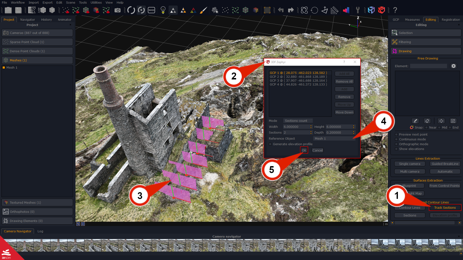
The new sections will be listed in the “Project” tab.Here below the Track section generation applied to a mesh:
Contour lines generation
Click the “Contour lines” (1) button from the Editing tab > Drawing elements, or click Tools > Sections and Contour lines > Contour lines to start.
The Contour lines settings window (2) will pop up while a group of blue planes (3) will overlap the 3D model in the workspace.
Select the Target object (4) and adjust the blue planes’ size, position, and rotation using either the gizmo (5) or the Contour lines settings window (2).
You can also define the plane’s depth and step (these thresholds get metric units when the 3D model has been scaled). Please, consider the number of contour lines will change as the step value varies and vice versa.
Note: the initial planes’ size depends on the bounding box dimensions.
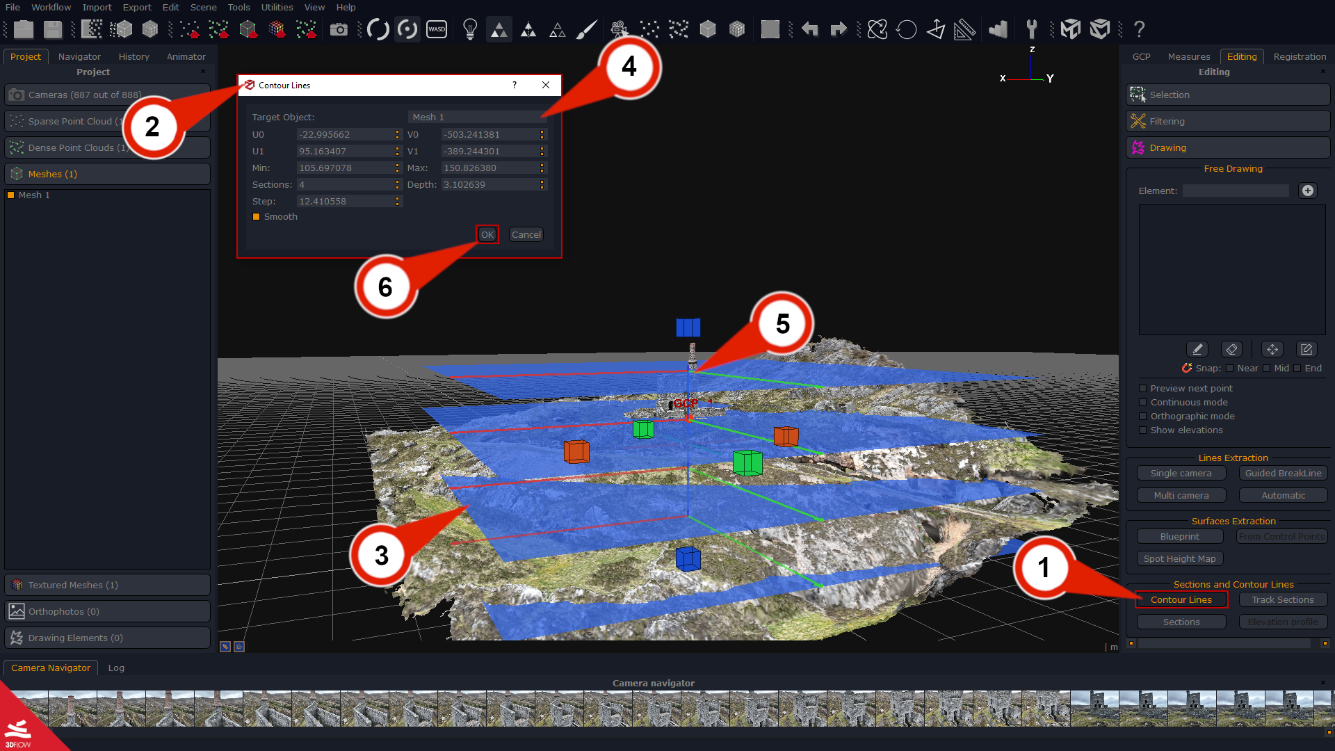
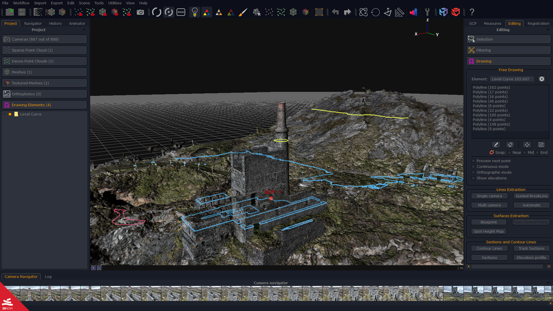
Press the “OK” (6) button once you are set. Here below the Contour lines generation applied to a mesh:
Section/track section/contour lines generation from Dense Point Cloud
When you click the “Ok” button in the sections/track sections/contour lines settings window and select a dense point cloud as the target object, an editor window pops up automatically.
That editor allows you to automatically create sections and contour lines and modify them by editing every vertex of the polylines representing the sections and contour lines that will be imported into the workspace once you are done with the editing.
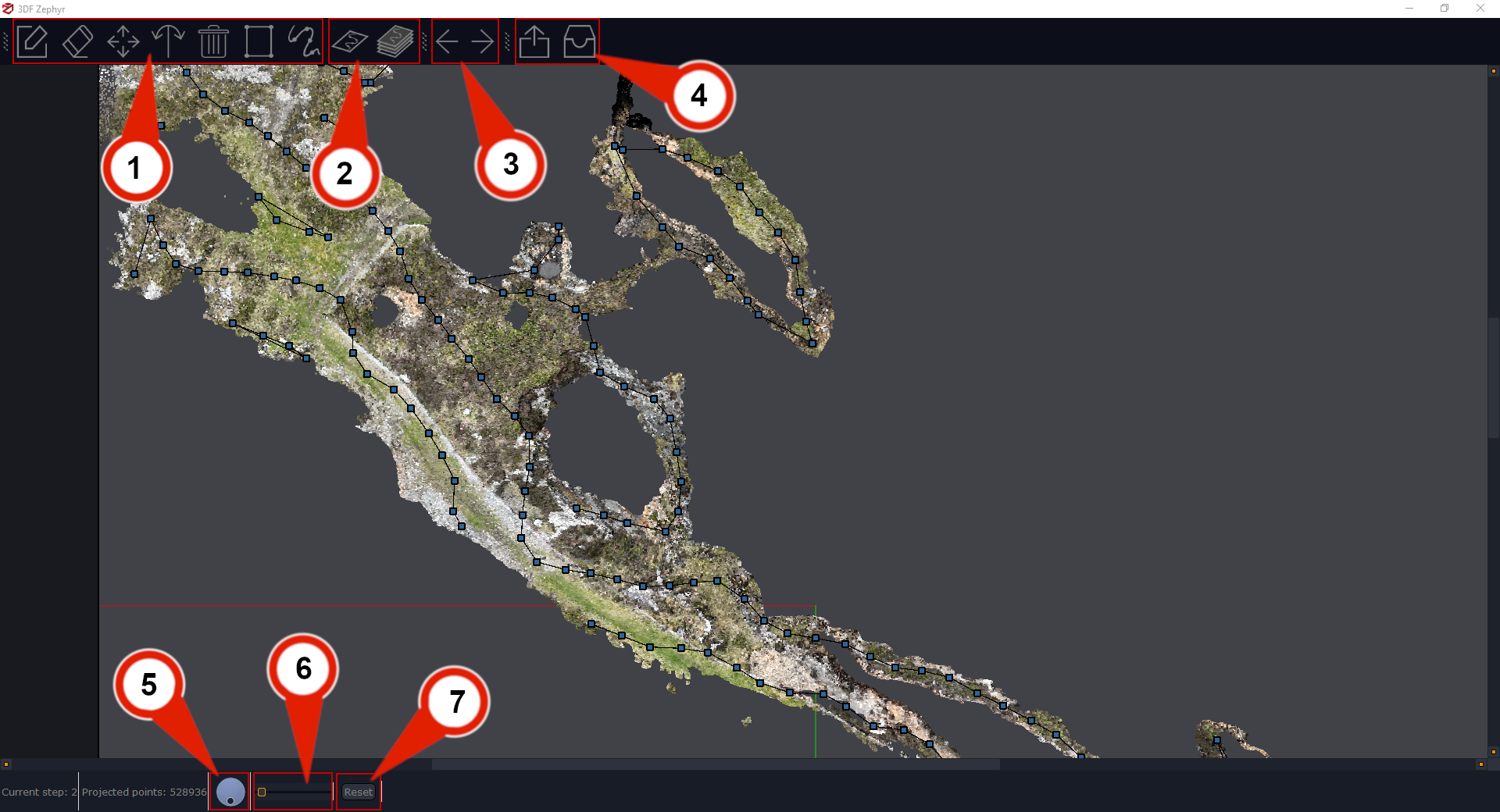
- Editing tools (1) – create, remove, move, split, clear vertices of a section, and close or smooth a section;
- Automatic generation (2) – automatically generates the current section or all the sections at once;
- Switch section (3) – switch to the previous or next section;
- Export/Import (4) – export sections and contour lines to .dxf and .txt formats and import the drawing elements into the Zephyr workspace,
- Rotate (5) – rotate the view;
- Zoom (6) – zoom in or zoom out on the current section;
- Reset (7) – reset the current zoom and rotation;
Click the “import” icon to bring the sections/track sections/contour lines into the workspace once you are done with the editing.