Tutorial #A2 : orthophoto generation
Orthophoto Generation Workflow
Welcome to the 3DF Zephyr tutorial series.
In this guide, you will learn how to generate and customize an orthophoto with 3DF Zephyr.
This tutorial cannot be completed with 3DF Zephyr Free or Lite versions!
Summary
Introduction
3DF Zephyr allows to generate true orthophotos from a mesh or creating orthomosaics from a sparse or dense point cloud. To explore this topic further, you can check out this quote from Wikipedia:
An orthophoto (or orthomosaic) is a geometrically corrected (“orthorectified”) picture whose scale is uniform. The photo has the same lack of distortion as a map, and, unlike standard images with a certain level of perspective, an orthophoto allows measuring true distances.
You must create a (scaled and georeferenced) point cloud or mesh in your project before generating an orthophoto in 3DF Zephyr.
Section A: Generating orthophoto via new project wizard
The primary method for generating orthophothos in Zephyr, it’s directly from the Z-axis during the new project creation wizard.
On the initial page of the project wizard, select the Orthophoto phase from the available options in the scheme.
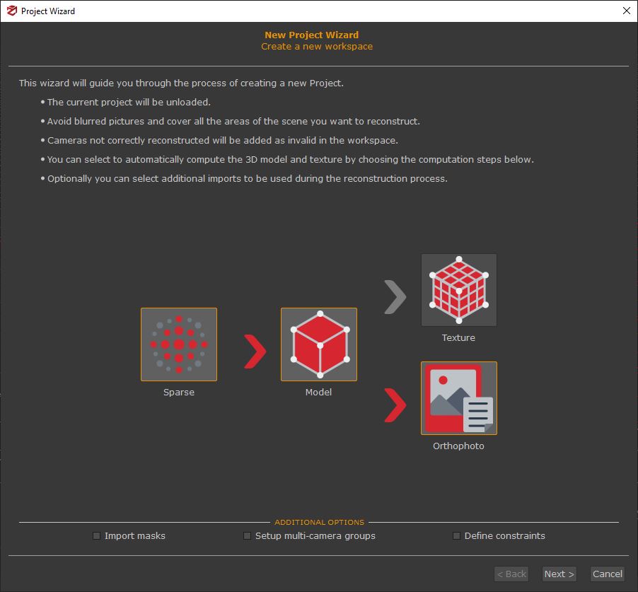
By clicking the “Next” button, you can navigate through the wizard’s pages until you reach the orthophoto settings page.
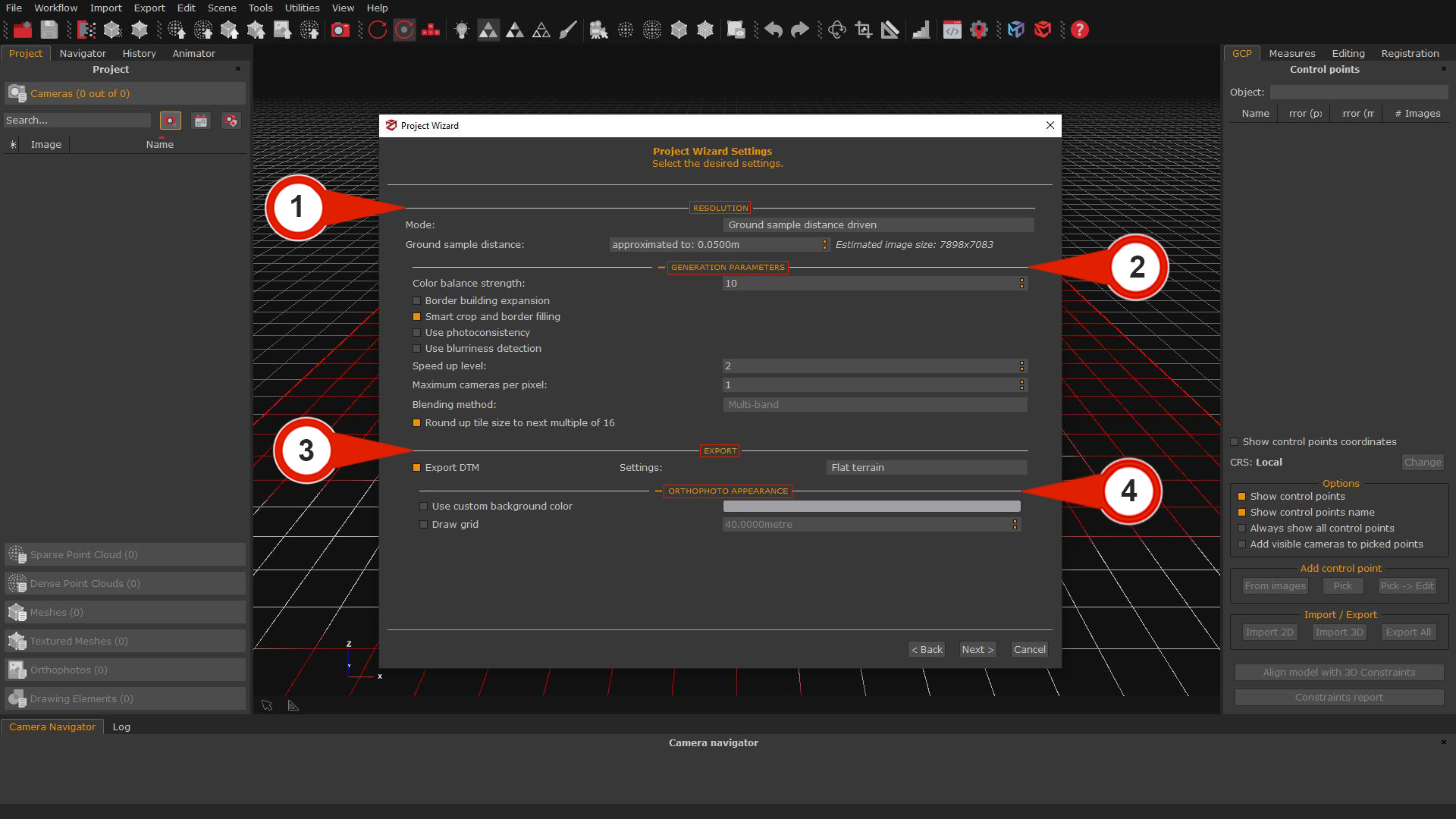
RESOLUTION SECTION (1)
In this section, it’s possible to decide how Zephyr will calculate the resolution in the Mode drop-down menu by selecting between “Ground Simple Distance Driven” or “Image Size Driven” therefore, define either the Ground Sample Distance or the Image Size (largest dimension) of the orthophoto.
Note: The 3Dflow Ground sampling distance calculator can be used to find the best GSD in relation to the resolution of your images.
Follow this link to use the calculator: https://www.3dflow.net/ground-sampling-distance-calculator/
GENERATION PARAMETERS SECTION (2)
It allows controlling every pixel’s color generation mode and other tweaks. This system is very similar to the texture generation system. We advise leaving the color balance with 1 camera per pixel; however, if you wish, you may use more cameras for a different color weight. If this happens, you may choose between an algorithm blending method:
- – Multiband: will use the Mean to compute low frequencies and the best images to compute the high frequencies. This is usually a better choice than Mean because although it is less prone to lighting changes (usually just a little worse than Mean), the resulting image will be more in focus and sharp by preserving high frequencies.
– Mean: will weight the color source depending on the view angle and the distance. Although it’s robust to lighting changes, the Mean won’t keep high frequencies, so will be less in focus and sharp.
EXPORT SECTION (3)
Export DTM: selecting this flag will automatically generate a DTM (Digital Terrain Model) file according to the scene type. It’s possible to choose three different scenarios (Mountain area, Complex scene, and Flat terrain).
ORTHOPHOTO APPEARANCE (4)
this section enables/disables the drawing for customizing the control points and grid on the orthophoto if desired.
Following the reconstruction process, the orthophoto will be displayed in the Orthophoto section of the Project tab.
Section B: Generating orthophoto after the new project creation
Step 1 – Setting the orthophoto’s source
You will notice different orthophoto generation options from the “Workflow” Menu:
- Orthophoto from sparse points (requires generating sparse points cloud).
- Orthophoto from dense points (requires generating dense points cloud).
- True Orthophoto from Mesh (requires generating the mesh).
By selecting the True Orthophoto from Mesh (1) option, the Orthophoto Wizard window (2) will open, and a Bounding box (3) appears in the 3D workspace.
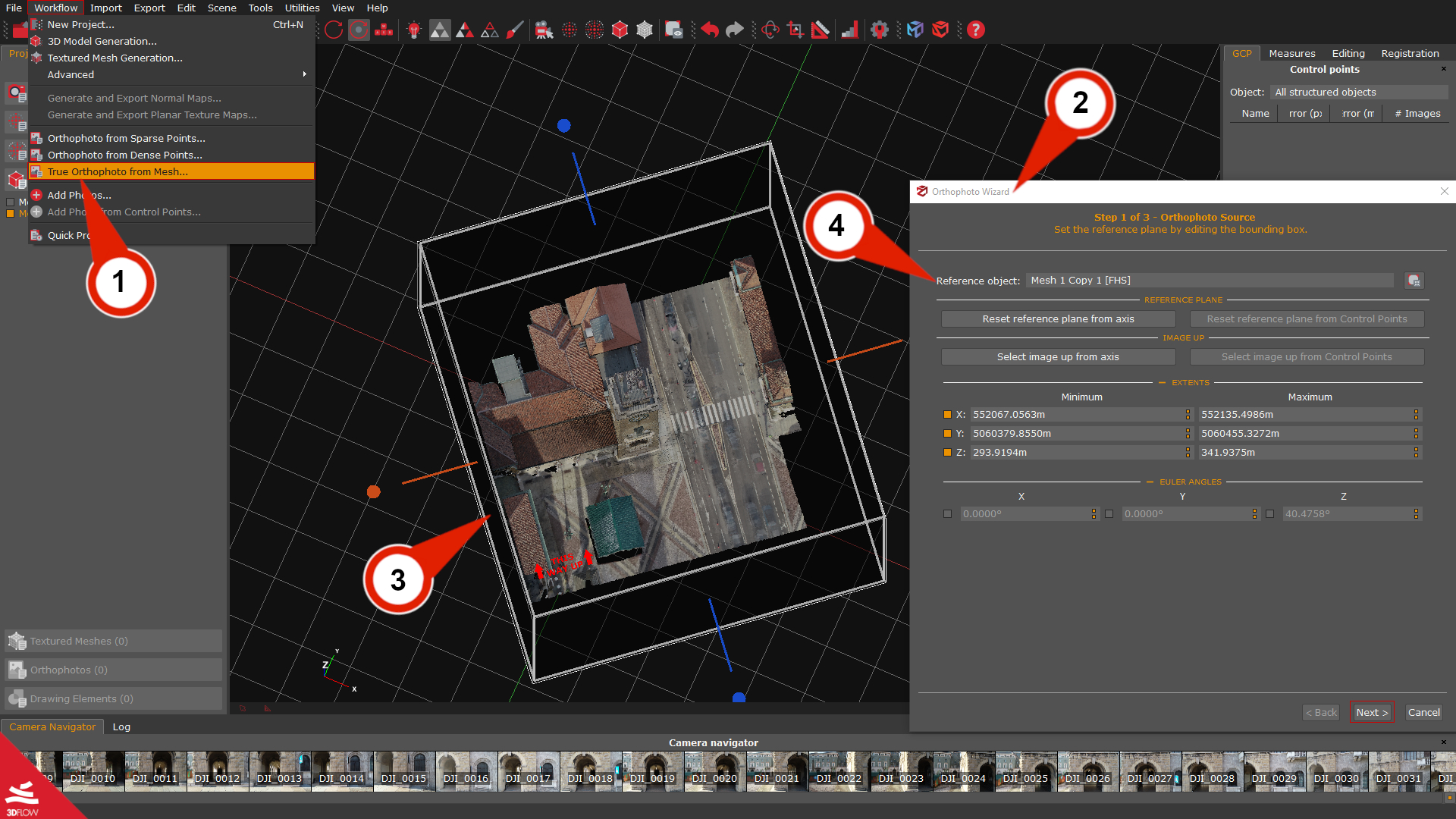
On Step 1 – Orthophoto Source page, you can define the boundaries of the orthophoto by changing the dimensions of the bounding box in the workspace and also set the reference plane from another axis or at least 3 GCPs. It’s possible to select another Reference object (4) among the created meshes. The button Adapt bounding box allows changing the bounding box size of the mesh automatically.
The default settings of the Orthophoto Wizard will create an orthophoto of the whole 3D model with the reference plane on the Z axis; if this is the desired situation, press the “Next” button and proceed to Step 2 page.
Changing the orthophoto’s reference plane
The workflow below will allow setting the reference plane using GCPs for creating an orthophoto’s facade. While changing the reference plane or the image up direction, it will be possible to see a preview on the bounding box represented by the red text: 🠝THIS WAY UP🠝.
Note: it’s best to change the Reference Plane and Image Up directions first, as this will reset the bounding box size each time.
At least 3 control points must be placed before with the GCP placement tool: “From images” (available on the GCP panel) on the mesh to define the plane of the orthophoto.
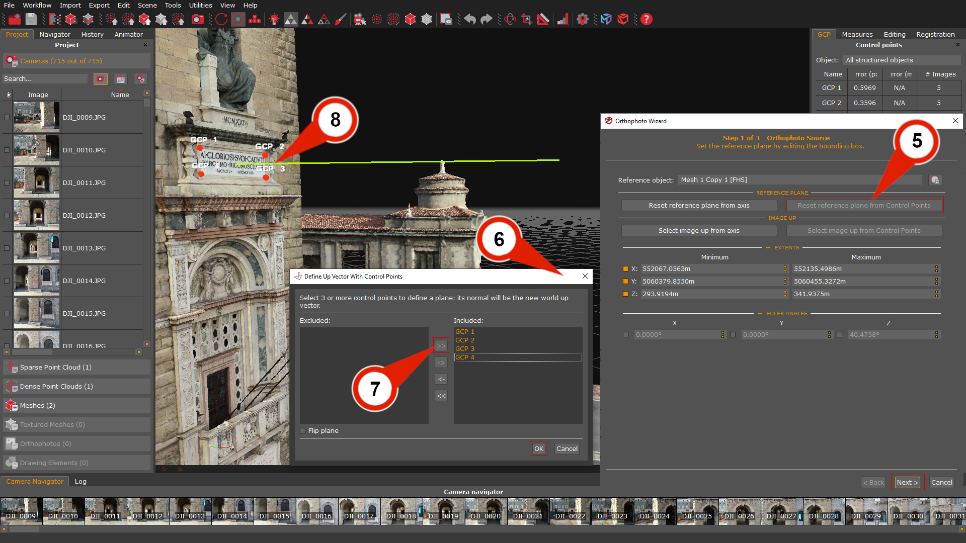
Click on the “Reset reference plane from control points” (5) button to open the Define up vector with control points (6) window.
Select 3 or more control points (7) to define the orthophoto’s plane. As a preview during the GCP’s placement, a yellow line (8) will represent the normal’s direction in the workspace.
After clicking the “Ok” button, the GCP’s plane normal will become the new world-up vector.
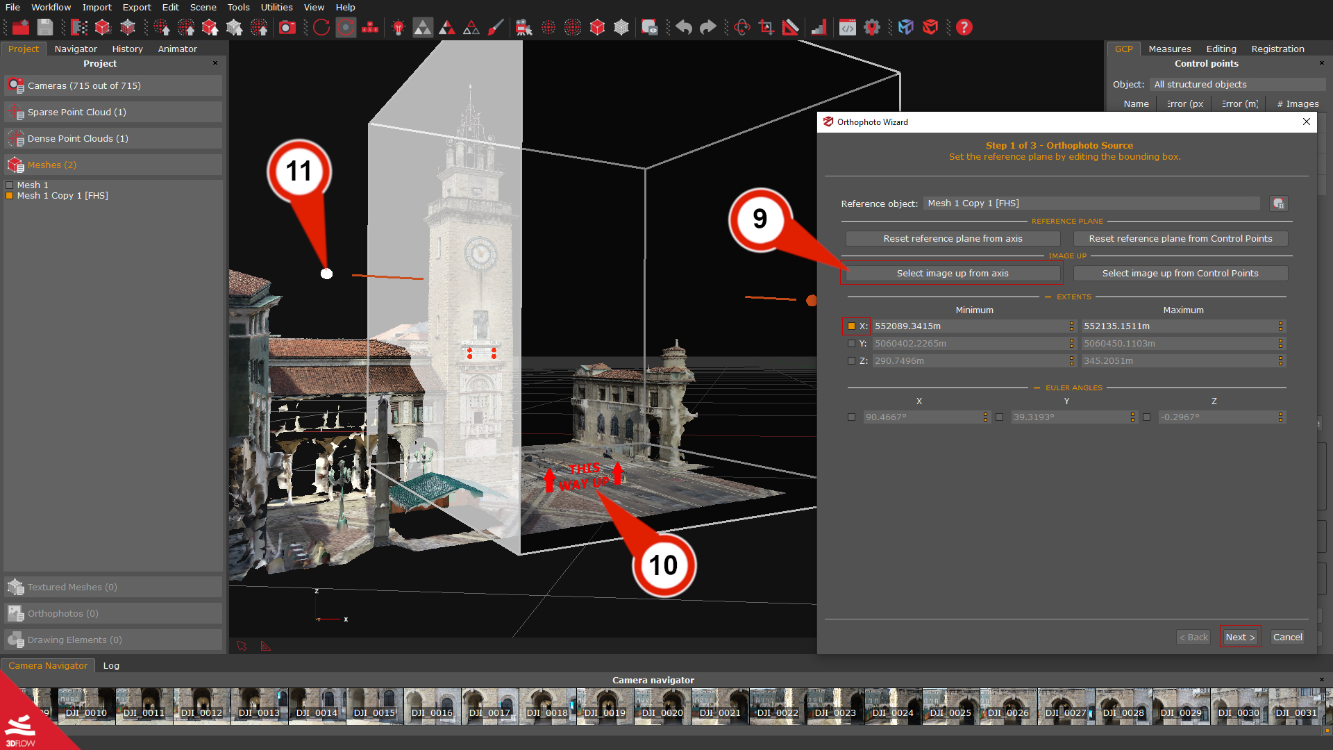
We can also use the “Select image up from axis” (9) function to choose the axis for orienting the orthophoto’s image up direction.
The red text: 🠝THIS WAY UP🠝 (10) will preview the new plane orientation on the bounding box.
The orthophoto borders can be decided by Setting the bounding box in the viewport (11) or changing the parameters in the Extents and Euler Angles sections. Through the checkboxes, it is possible to restrict one or more axes on which to move or rotate the Bounding Box.
Once the source of the orthophoto has been set, you can continue with the “Next” button.
Step 2 – Choosing the orthophoto resolution
The Step 2 – Resolution page of the orthophoto wizard will present a set of options to define the orthophoto resolution by changing the Ground sample distance (GSD), specifying the image size, and Generation parameters for controlling pixel’s colors. The Camera to use section allows the choice to ignore cameras during the generation process by cameras directly or by tags.
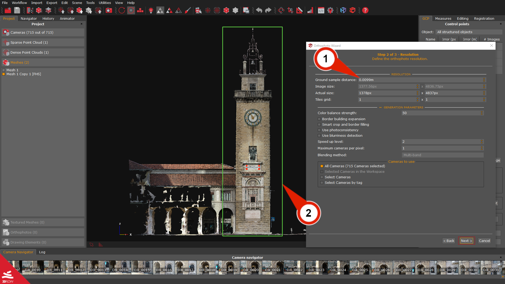
The orthophoto Width and Height can be adjusted according to the desired Ground Sample Distance (1), or you can set the GSD directly and let 3DF Zephyr calculate the resolution for you. The workspace will show a preview, while the green rubber band (2) will define boundaries within the orthophoto image.
The Step 3 page will be available by pressing the “Next” button.
Note: The 3Dflow Ground sampling distance calculator can be used to find the best GSD in relation to the resolution of your images.
Follow this link to use the calculator: https://www.3dflow.net/ground-sampling-distance-calculator/
Step 3 – Export settings
This section allows choosing the export settings and the appearance of the orthophoto.
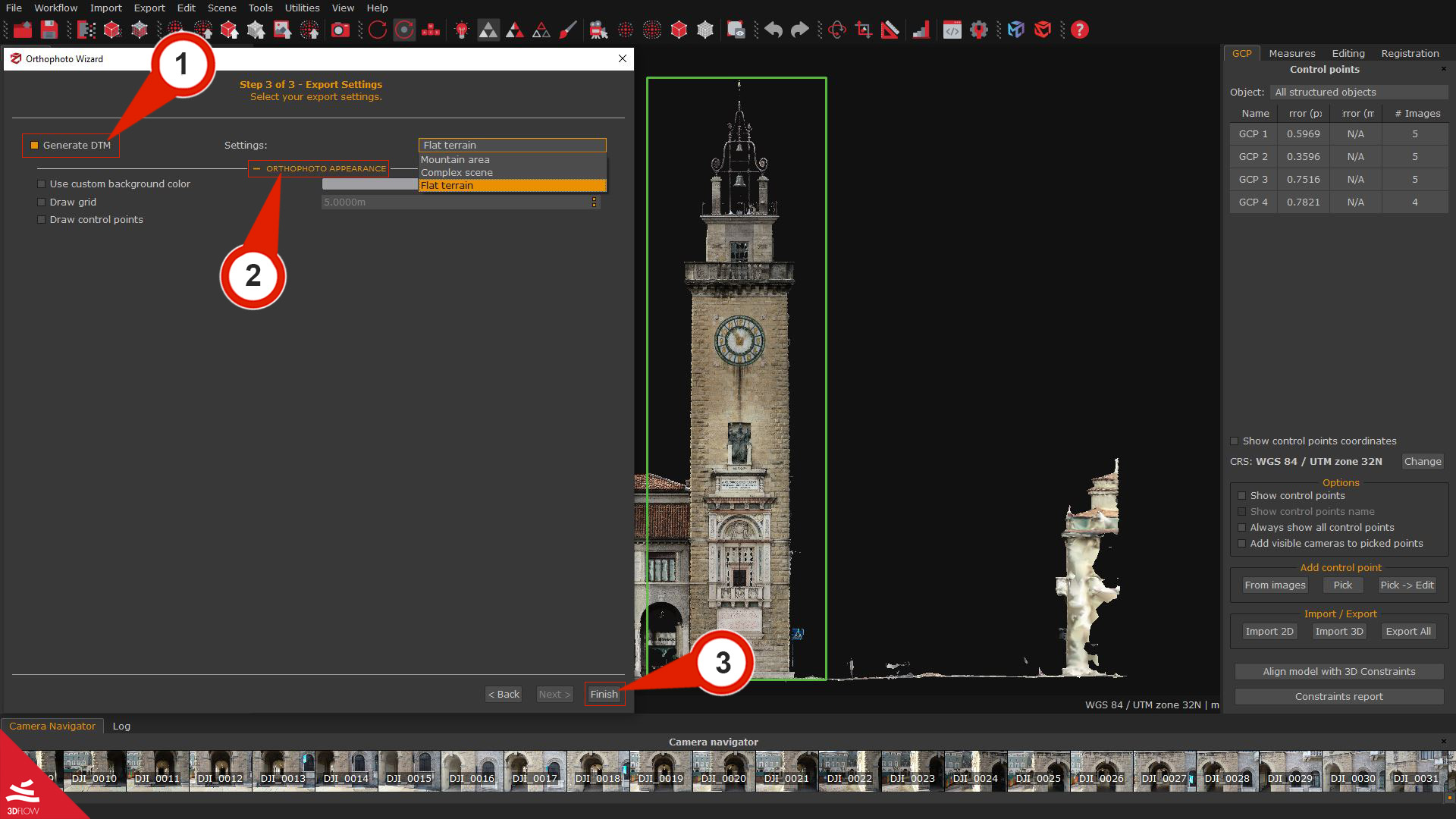
The Generate DTM (1) checkbox can be checked depending on the scene type. Three scenarios are available: (Mountain area, Complex scene, and Flat terrain).
Orthophoto appearance (2): this section enables/disables the drawing for customizing the control points and grid on the orthophoto if desired.
When everything is ready, click “Finish” (3) to launch the orthophoto generation.
Following the reconstruction process, the new orthophoto will be available on the right in the Orthophoto section of the Project tab.
Note: Zephyr will automatically open its DEM Viewer utility when the process is complete and will be possible to view the orthophoto, and DSM overlaid.
Save the orthophoto on the computer
At the end of the generation process, the new orthophoto will be listed in the Project tab under the section Orthophoto.
By right-clicking on the orthophoto will be possible to choose the option “Export” (1), and the Export orthophoto (2) window will appear. It’s possible to choose different export settings; see the description below:
The Export (3) drop-down menu offers the option to export only the orthophoto, the DSM, DTM, or all the files.
The Image format (4) drop-down menu allows you to save the Orthophoto in these image formats: *.jpg, *.png, and *.tif.
As additional export possibilities, the following checkboxes will allow you to export additional file formats as needed.
- – Export Pdf file: allow to export the orthophoto in Pdf format.
– Export KML file: enabling this checkbox, allows to export an orthophoto in .kml format for Google Earth.
– Export Autocad script file: enabling this checkbox, allow to export a .scr file that can be automatically dragged into the Autocad workspace and will allow exporting the orthophoto with the correct scale set in 3DF Zephyr.
– Export World file: exports the World file.
The Tiff pyramids level parameter will allow storing inside the generated Tiff orthophoto a pyramids levels layers, which can improve the display of raster data by retrieving only data at a specific resolution required for display.
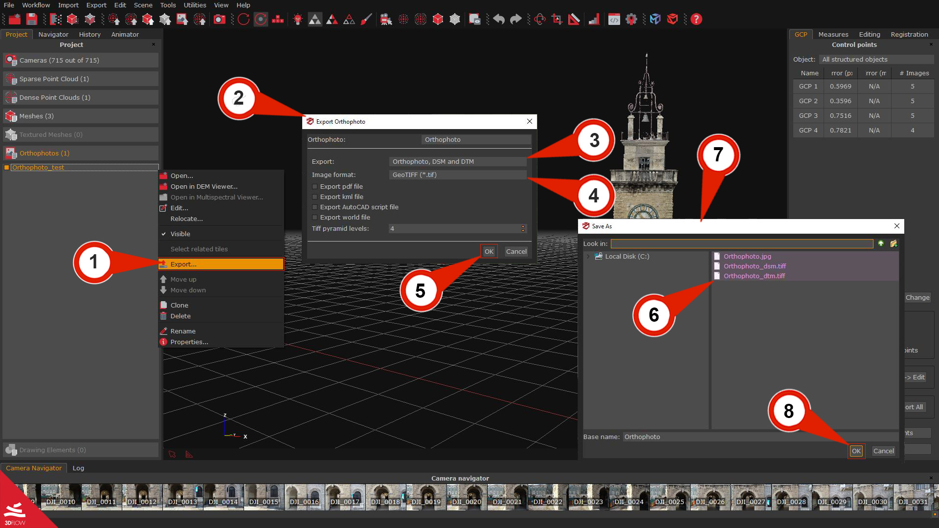
After establishing the parameters for saving the orthophoto, click “OK”(5). A preview (6) of the exported files will be shown in the Save As (7) window; select the file name and destination folder, and then the “OK”(8) button to save.
Final notes
In the Verruca Fortress case study; you can see an example of how the orthophotos created in 3DF Zephyr can be used in an applied scenario.