Getting started with 3DF Zephyr
Welcome to the 3DF Zephyr tutorial series. In this tutorial, you will learn the basic steps for turning pictures into 3D models with 3DF Zephyr.
IMPORTANT NOTE: The images in the following tutorial describe the full version of 3DF Zephyr, showcasing all its features. Please note that 3DF Zephyr Free and 3DF Zephyr Lite follow the same workflow for 3D reconstruction, but not all options may be available. You can consult the 3DF Zephyr Feature Comparison page to view all available features in each version.
Summary
Introduction
Return to summary
Creating 3D models from pictures in Zephyr requires a dataset of images taken using photogrammetry techniques. You can use your own pictures by following this tutorial. Please refer to these base guidelines to learn the best practices for acquiring a photogrammetry dataset. Note that the image acquisition phase is crucial for successful photogrammetry reconstruction.
NOTE: before starting a photogrammetry reconstruction in 3DF Zephyr, it is important to provide a reliable dataset. Avoid using blurred images and datasets with no overlapping pictures, as these can lead to poor quality reconstructions. Please never crop, cut, or edit the pictures in Photoshop or other image editors.
If don’t have your pictures yet, you can use our sample dataset below. Please download the Dataset – Cherub zip file and extract it on your computer.
This dataset is composed by 65 photos, if you’re using 3DF Zephyr Free, which is limited to 50 photos, simply select the first 50 photos only.
 | Download Dataset – Cherub (531MB) |
 | Download – Cherub .ZEP file (340MB) |
If it hasn’t been done already, the following links are available for downloading and installing the suitable version of 3DF Zephyr to start the tutorial:
Step 1 – Creating a new project
Starting the new project wizard
Return to summary
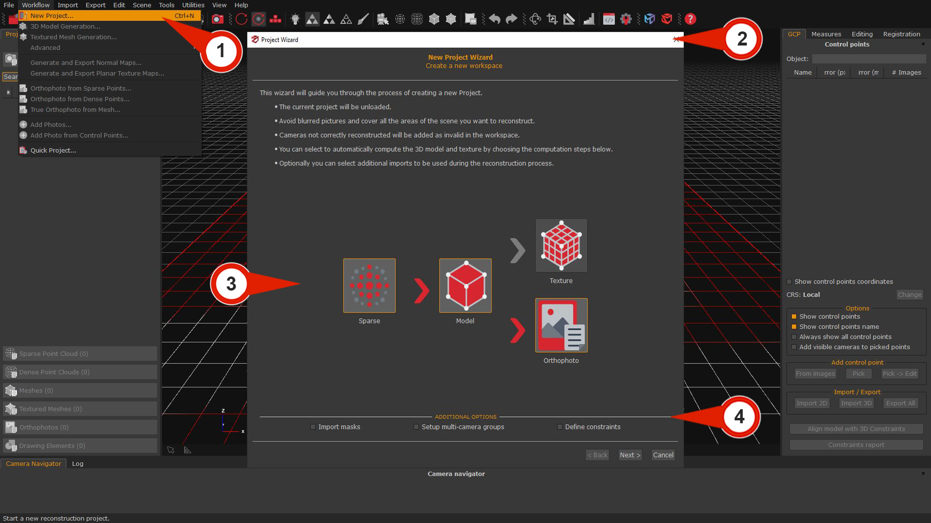
To create a new project, click on “Workflow” > “New Project” (1). The Project Wizard (2) will guide through the picture import and camera orientation phase setup. It’s possible to select the required 3D reconstruction phase(s) in addition to the camera orientation phase by enabling the corresponding icons in the Computation steps (3) graph.
- SPARSE: This option will orient the images and generate a Sparse point cloud.
- MODEL: This option will create the Sparse point cloud, Dense point cloud, and Mesh.
- TEXTURE: This option will include all the previous 3D products and generate a Mesh with texture.
For example, enabling the “MODEL” icon will result in the software completing the Sparse point cloud, Dense point cloud, and Mesh generation before stopping and allowing selection of the Textured mesh generation.
Depending on the version of Zephyr used, the Additional option (4) section can include the following check-boxes: Import of image masks, Define constraints (2D and 3D coordinates), and Setup of multi-camera groups.
If the additional options are not needed, simply click the “Next” button to proceed through the wizard.
Note: only in 3DF Zephyr Full version, it’s possible to decide in the final phase whether to generate a Mesh with texture or an Orthophoto on the Z axis. For the advanced orthophoto workflow, follow this link: Section A: Generating orthophoto via new project wizard.
If only the Sparse Point Cloud creation phase (“SPARSE” in the graph) is chosen, it is still possible to start the other phases subsequently from the Workflow menu selectively. Here is a brief description:
- 3D Model Generation: Creates a dense point cloud and extracts the mesh in a single step.
Requirement: Sparse point cloud - Texture Mesh Generation: Creates a mesh with texture.Requirement: Mesh
From Workflow > Advanced, the following options will be available:
- Dense Point Cloud Generation: Creates a dense cloud.
Requirement: Sparse point cloud - Mesh Extraction: Creates a mesh with RGB colors.
Requirement: Dense point cloud
Selecting the images
The next window will present the Photo selection page, where you can add images to be processed by Zephyr.
Click on the “Add directory” (5) button, browse to the directory where your dataset is located, and then press the “Select folder” button. If there are subdirectories in the folder, Zephyr will prompt you with a pop-up window to include them in the wizard by clicking a “YES” or “NO” button. You can also drag and drop images or folders directly into the Photo selection space.
Alternatively, you can click the Add images (6) button, browse to the directory where your dataset is located, select all the images you previously extracted, and then click the “Open” button. If needed, you can select one or all images (ctrl+a) and click the “Remove” (7) button to exclude them from the workflow.
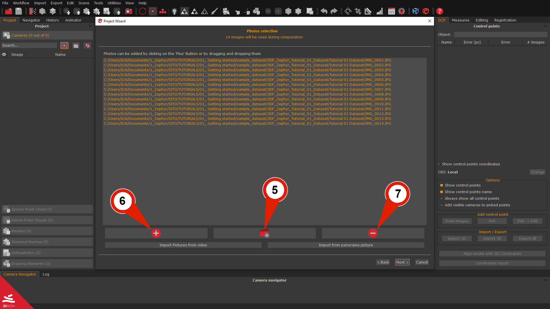
Usually, most datasets are created using .JPG or .PNG files, but Zephyr can also use many other image formats, such as raw files (NEF, CR2, ARW2, etc.).
When all the pictures are selected, press the “Next” button to proceed to the following wizard page.
Camera calibration phase overview
Return to summary
Once the data to be processed is selected, the Camera Calibration page will appear. Here, it is possible to Add a New Calibration or Modify the Calibration that 3DF Zephyr has automatically selected.
The interface will display a list of the imported pictures along with their calibration summary, which 3DF Zephyr and its Structure from Motion algorithm will specifically utilize. When connected to the internet, 3DF Zephyr can download pre-calibrated camera parameters to speed-up the processing. However, the software is fully auto-calibrated, allowing it to function offline, and in most cases, all the parameters can be left as default.
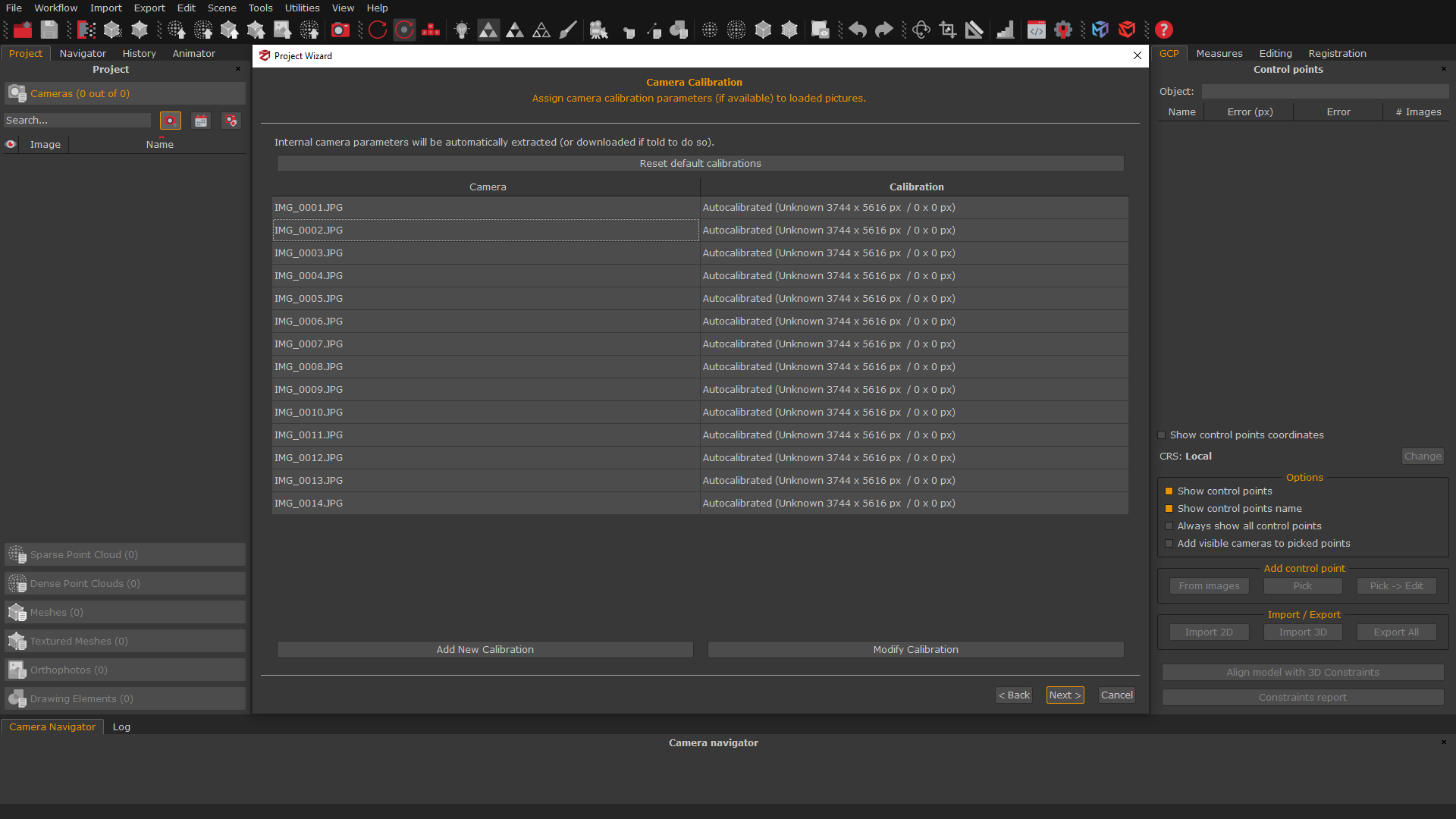
Click the “Next” button to proceed to Step 2: Configure the reconstruction settings.
Step 2: Configure the reconstruction settings
In this step of the tutorial, the settings pages of 3DF Zephyr will be illustrated. Depending on the 3D reconstruction phase(s) chosen in step 1 of the tutorial, the respective setting pages will consistently appear.
Camera orientation and sparse point cloud generation
Return to summary
The first phase of 3D reconstruction is called Structure from Motion and computes the position and orientation of each photo loaded in Zephyr. This step results in a Sparse point cloud.
The software analyzes each image, identifies its features, and compares each image with (usually a subset of) the other pictures. This process is used to set the cameras in the correct position.
Users must define the Category depending on the scenario/subject they have captured and select the Preset according to the accuracy and quality level they want to achieve on the 3D model(s).
Click the “Next” button to proced.
For this tutorial, the following settings will be used:
Category
- :
General
Preset
- :Default settings.
IMAGE
The Advanced settings mode allows to “tweak” the reconstruction engine process. It’s possible to switch from Preset Mode to the Advanced settings by clicking the drop-down menu in the upper right corner of the window.